Yet another way to spend money on something that’s fun to do but may not be worth it in the end
I wrote a somewhat lengthy Facebook post about this project and realized that I needed to drop it here, too.
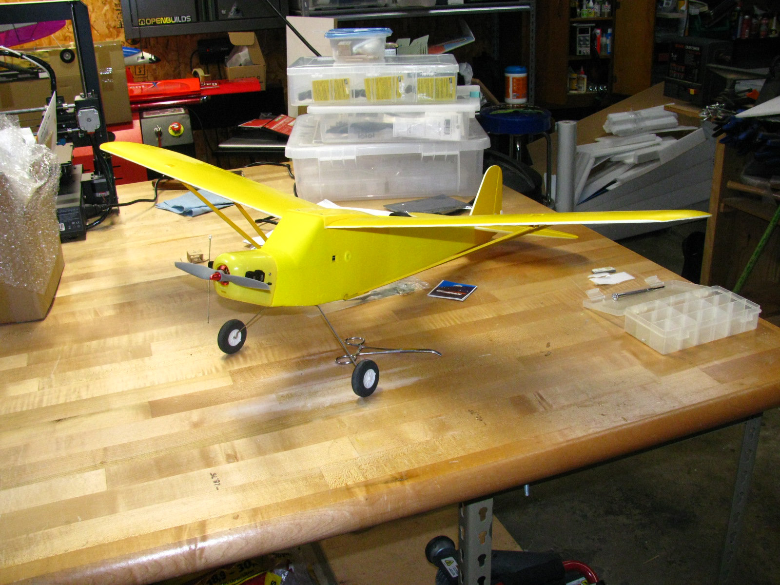
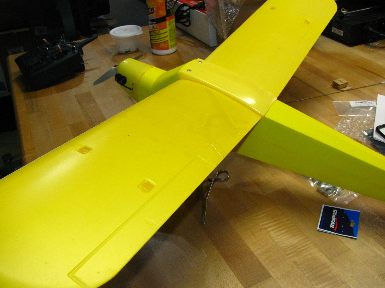
Finished up a “distraction project” from the Bob Wade legacy this afternoon.
Apparently, Bob Wade had a go at converting a Harbor Freight toy RC plane to brushless that hadn’t ended well. The port wing panel was fractured out and he had apparently just cut the pushrods short when extracting the servos from the carcass.
An old TowerPro brushless motor was in the nose on a pieced together plywood box, which kind of tells me where things went wrong. It was just too much motor for such a small plane and, given the probable time frame, I’m betting the battery pack to feed it wasn’t a very good fit.
In any case, if I’d had more sense I probably would have just chucked it into the burn pile and been a richer man.
Yeah. Well.
The wing and tail are made from what is essentially Depron that’s surfaced with a thin layer of plastic laminate. There was just something about the wing damage that I couldn’t leave alone. I knew I could fix it.
And that’s what I did. I brought it in from the Hangar to fix the wing. Turns out that Gorilla Glue Clear non-foaming worked great at not only putting the jigsaw pieces back together again, but it also formed a new skin that bonded with the old skin. It was a great fix. (Also, I used some new polyester plastic sheet I just got as intended plans protector to work as ersatz Mylar to make the skin smooth while the glue cured. That really helped.)
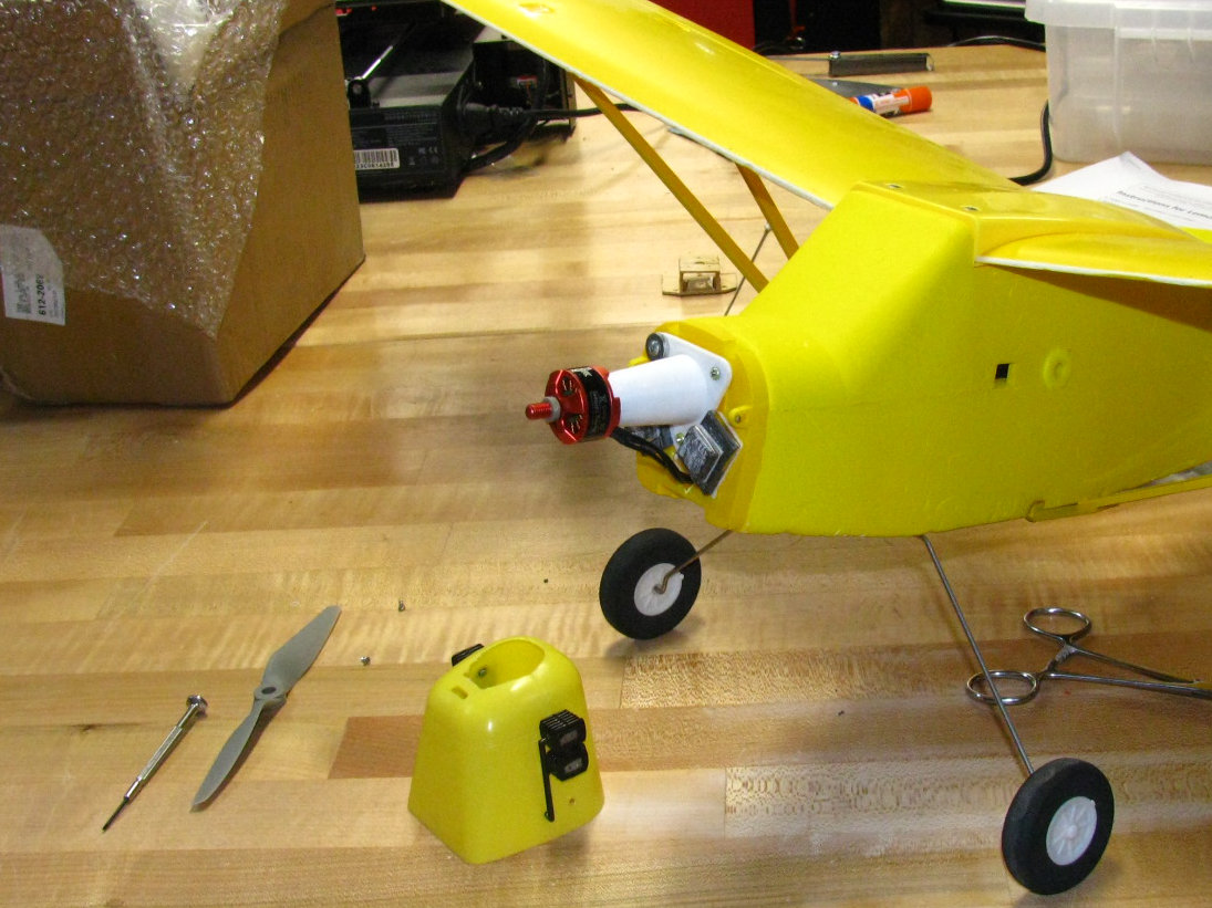
Once the wing was fixed, I was stuck. My urge to fiddle and fix had been released.I sourced a little drone motor from Willy Nillies to replace the ginormous TowerPro, ordered 800 and 850 mAh 3s packs from RCBatteries, and dug out and tested two scavenged MX-50 servos from the scrap bin.
Shiny new 1/2A 1806 from Doug and Becky attached to an ABS printed mount
One of the old push-rods was re-usable. The other I replaced with a 1/16″ wire fab. Du-Bro EZ connectors went on the servo arms and that took care of actuation.
I had procured a stock of Lemon receivers a while back and broke one out for this project. Got it bound and set up. Added a HobbyKing 12 amp speed control with XT-30 connector.
I also fired up the 3D printer to make a replacement motor mount that would put the motor just proud of the cowling. Took several print attempts to re-learn what I needed to make it work, but work it did eventually.
Because of the layout of the model, I ended up having to add 1.5 ounces of lead to the firewall to get it to balance, which is annoying. Unfortunately, pushing the battery pack into the nose just wasn’t feasible without compromising the hard plastic inserts for the battery bay.
It’s done. Everything works like it should and the balance seems reasonable. Will try to get it out to the field Friday evening or Saturday afternoon before the ball game to see if I actually pulled it off.
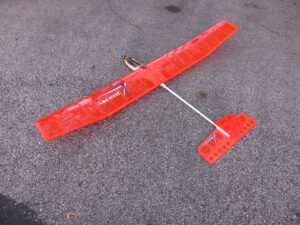
For those who don’t know/remember, the Ascent was a Tower/somebody ARF with a built-up wing, holes in the wood sheet tail, fiberglass fuselage and probably tail boom (it’s painted and I’m leaving it alone.)
The power came from some off-brand S400 canned motor. Slot in the fuselage was set up for a 7 or 8 cell pack. Came with the classic crap-tastic Chinese folding propeller.
The thing sat in a box for a good long time until I got some time and interest strung in a row to slap together the wing and tail and hot glue in a couple of MX-50 servos since the wells had been sized from some unobtainium micro that wasn’t one of the dozens in my stock.
Then Something happened and I never flew the bloody thing.
Jump forward again, and nobody is flying canned 400s anymore and old-fashioned KR600 packs are rare. Weirdly, being incredibly incapable of letting things go, I still had some 8-cell packs, new-old stock with no connectors. So I slapped a connector on the end, dug out a 20 amp controller, and strung a new Spektrum receiver in the thing to see what flying old school was like.
It sucked. Heavy. Low power. doggy. I think it was mostly because the motor was some non-Graupner motor of whatever voltage was available for production at the time, since I did cycle the pack and it was okay. It flew, but not in a fun way, especially when the crap-tastic Chinese prop decided to part ways with the yoke and pop the motor mount out of the fiberglass fuselage.
So, after re-seating the motor mount, I dug around in my project box and found a speculation motor I’d picked up at Phil’s back in the day. Apparently there was a pusher model called the F-27 that used an in-runner hotrod motor that just happened to bolt into a S400 motor mount. So I picked up a 25 amp Hobby King speed control, stuffed an 1800 mAh 3S pack in (it fit in the slot), chucked an Aeronaut 7×4 folder on the front and committed aviation again.
Okay, this time it flew like hell-bat out of-one each. It also sank like a brick with the motor off. And the way the prop was talking, I knew I was pushing my luck. Got it back down and found the prop pivot bolts had been bent. Eep.
So, too much of a good thing. Ascent went back into the corner and I started playing with ideas regarding batteries and motors.
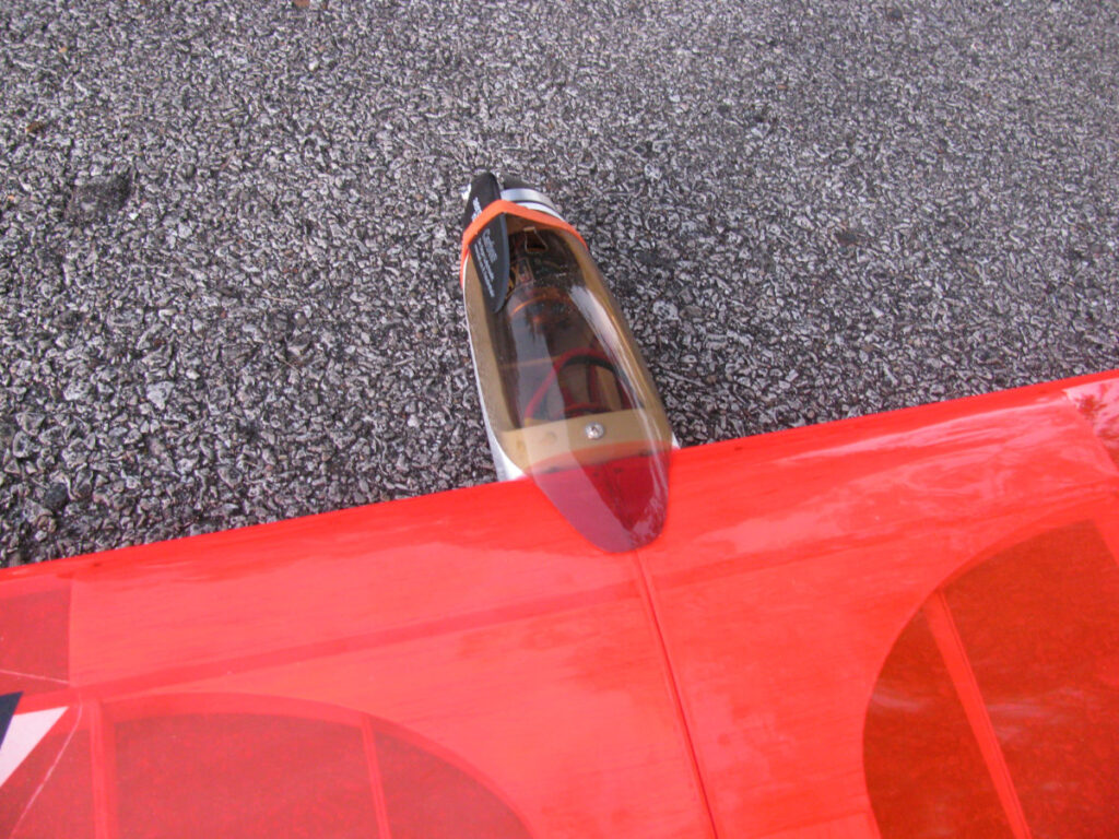
Espritech happened to have some sales going on a while back on AXI motors. I went ahead and speculated on motors again because, apparently I’m addicted to buying expensive things to put in boxes on shelves. In this case, however, I managed to grab an AXI 2217/20 long can motor. And it turned out that, after thinking things through, it was actually just what the Aspire needed.
Now, mind you, this meant having to order a prop/spinner adapter from ENGLAND because, “There’s no market for a 40 mm spinner with a 3.17mm shaft motor” per the people who sold me the motor with the 3.17mm shaft. Regardless of that, though, I was able to provide a set of 8×5 blades from my stockpile to go with my nice imported spinner. The speed control, receiver, and servos remained the same, but the battery downsized to a 1000 mAh 3S pack.
You can see the rotating back end of the AXI
I re-maidened the re-motored Aspire Sunday and then flew it again Tuesday at the weekly club get-together. I finally have a model that flies like a glider. My take away is that the weight really had to come down and I had to shift my mental focus away from a pack that was the same dimensions and actually look at the capacity and the motor draw instead.
The 1000 mAh pack drops into the 70% remaining capacity range during fairly active 8-10 minute flight and the performance is perfectly acceptable. Just need to improve the rudder throw a bit to improve yaw response. Elevator is great. Plane is really visible with its transparent red covering. That covering is also robust, as testified to the fact that it was not punctured when my tool box tipped over on it during the ride home Sunday when some idiot cut in front of me and forced a high-g deceleration maneuver. The structure has held up remarkably well, for as long as it’s been in storage. And even blowing the motor mount out didn’t do any significant damage to the fuselage: it just buggered up the gel-coat around the front edge as it exited.
Things I just don’t like about this airplane: Why is the canopy screwed on with little sheet metal grub screws into fiberglass? Who thought that was a good idea? And 4-40 bolts to hold down the back of the wing with easily lost and probably unobtainable 4-40 fender washers to spread the load? Especially when I think the trailing edge in the area the bolts goes through is hollow? Not the brightest.
The only thing I can really say about this is, some planes are just long, expensive journeys to get where they were supposed to be out of the box.
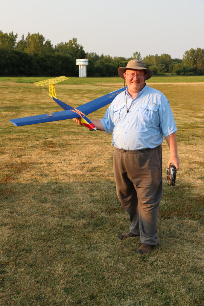
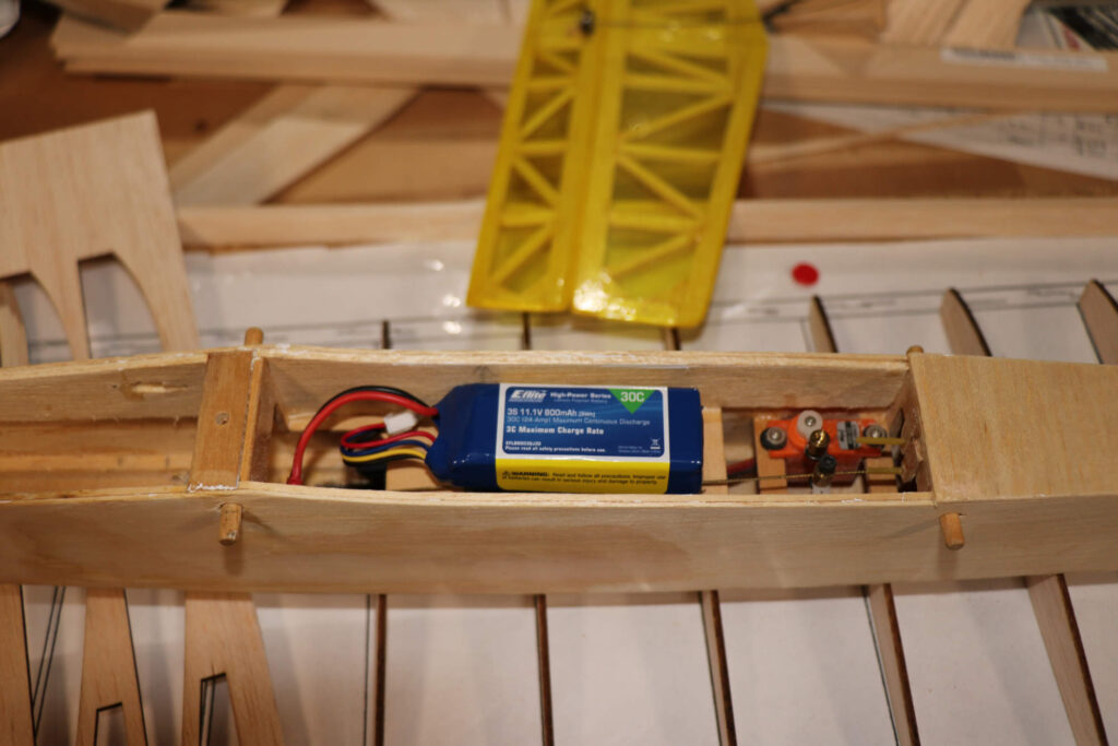
Well, the Skimmer rebuild saga is now officially over: The S’Timmer (T-tail Skimmer) had a wonderful and uneventful first flight this past Tuesday at the Lafayette Cloud Jockeys field Roll Call Tuesday gathering.
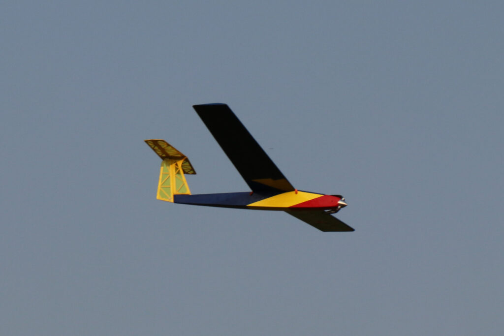
Da Current Big Guy and Da S’TimmerThe S’Timmer’s first fly-by
The down thrust built into the nose was definitely necessary as the bird pitches strongly up under full power.
Running 7×5 folding prop on 3S 800 mAh pack draws right at 10 amps static. It’s enough to make the bird really climb well, but not like a rocket.
Power off performance is light and responsive. I flew most of the first flight at 50% throws and it felt quite acceptable. I did bump the rudder up to 75% a bit at the end but it had to be handled carefully to avoid jerky flying.
Elevator is VERY responsive. I do not need anywhere near as much throw as I have and 50% D/R is just right.
This experiment just proves that Skimmers and even S’Timmers just fly right. They’re fun and responsive, little gliders that zoom.
All in all, a very satisfying project. Thanks for following along with the build.
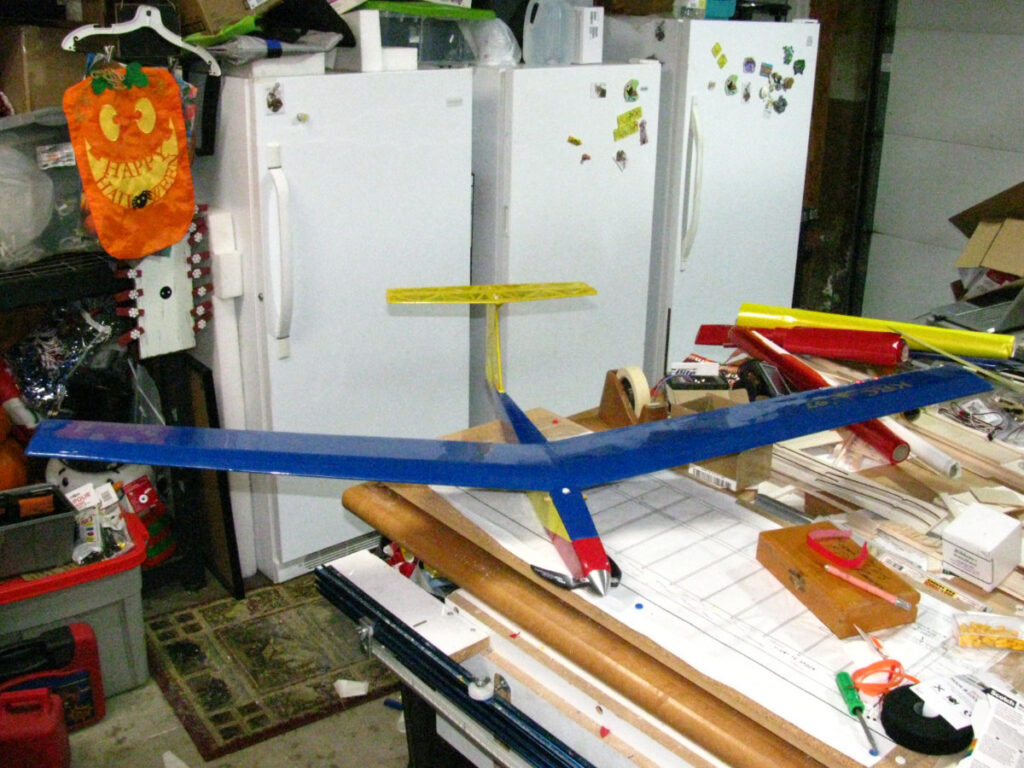
The covering is complete. The receiver is bound. The servos set up. The motor spins in the correct direction. The hatch screw is replaced and secured. The battery floor is reattached. All the surfaces wiggle in the right direction and I have WAY TOO MUCH throw. I’ll have to tame that a bit in the setup with dual rates.
It’s astounding how much time doing the little things correctly takes. For example, the stupid push rod tubes that I had thought were glued securely turned out to not be so, each on opposite ends. Fighting getting the Ultracote to go around the nose is always a chore, but getting it to stick inside the new motor hole was a challenge.
Then I had to run to the hobby shop for a JST connector that had a decent gauge of wire attached to it. I didn’t have 18 GA. I have 16 and 12. Not 18. I will rectify that in the future.
So, the parts that remained covered as-was from my Brother-in-Law: the hatch and the wings. The wings being original is important because the port panel has the original “KRC ’97” vinyl sticker on it.
The last thing to do is route a 3M Velcro strap around the battery floor. The 3S battery was too tall with the Velcro pads originally installed and the wing wouldn’t sit level. So I removed the old Velcro from the battery floor and the new Velcro from the battery pack and now there’s room. Unfortunately, I had to add something back to ensure the pack didn’t move and one layer of a Velcro strap should be okay as opposed to the extra thick “industrial strength” stuff that I was trying to use before.
Note about the laser control horns: I’m adjusting the laser layout to cut them on a carrier that will fit inside a standard small envelope/thank you card set. That will maximize the number of horns while minimizing mailing issues.
As a follow on to my visit with the Lafayette Cloud Jockeys and a pending September trip to Iowa to attend the Sig Fly-In, I am attempting to get some things in order so that I have some planes to fly. The Cloud Jockeys and LOFT both have an August 15 sailplane meet, as well, so I will be headed north to Fort Wayne since I am the VP for LOFT instead of joining the Cloud Jockeys at the South Field.
So, looking around, I attempt to define what I can achieve. The ever-durable Positron II is a sure bet, as is my woe-begotten Push-E Cat V5 development mule. I would like to finish the Miss Priss and parade that in public in September. The other oft neglected project is the old Skimmer 400 that I received from my brother-in-law a few years back that I am converting into a T-tail. That’s close enough to done that I think I can finish it for September, but not next Tuesday.
I have a 1.3 m Valiant that is 100% airworthy. All it needs is a charged pack. Ditto for a Night Radian. I have a micro F4F and a micro P-47 that I could fly Tuesday. Another pair of possibles for September are Pat Mattes’ old Ace Cessna knock-off that he threw together oh so many years ago and another inherited brother-in-law plane, a Nora originally acquired from Hobby Lobby in the dark ages of Speed 280 and Speed 400 gear drives. Both need upgrades to the current level of brushless/LiPo tech to be easily enjoyed.
Looking at it that way, I guess I do not feel so plane-poor after all. This leaves aside other more ambitious projects that will be recurring blog stories another time.
This post, however, focuses on the actual, real life progress I am making with the Skimmer.
Back in 2017, I started reworking the Skimmer 400. Will had brought the bird in hard on its nose at some point and things were completely shattered up front. Additionally, the empennage was basically Monocote bags of loose balsa sticks.
I got things rolling and was actually making good progress. I was a bit stumped on the motor and mounting, but I could have overcome that.
Then, my wife decided we were moving and things went all to heck and gone.
Now, in 2020, I’m finally getting my plow back in the dirt on this project.
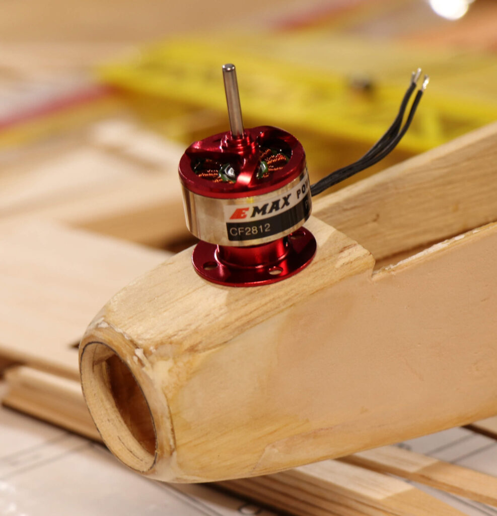
The winner: A Hobby King FC 28-12
The biggest thing was to get over my hiccup of choosing a motor.
As you can see here, I finally decided what to do and that was to go with Bell-style motors, 28 mm diameter, instead of a bulkhead type mount motor.
Updated nose for outrunner
The truth is that the 28 mm Bell-types are more flexible for my kind of modeling than the bulkheads. I like the fact that the mount can be bolted to the former without the motor and then the motor secured with set screws. That makes the whole thing very serviceable in my opinion, with a smaller mounting footprint.
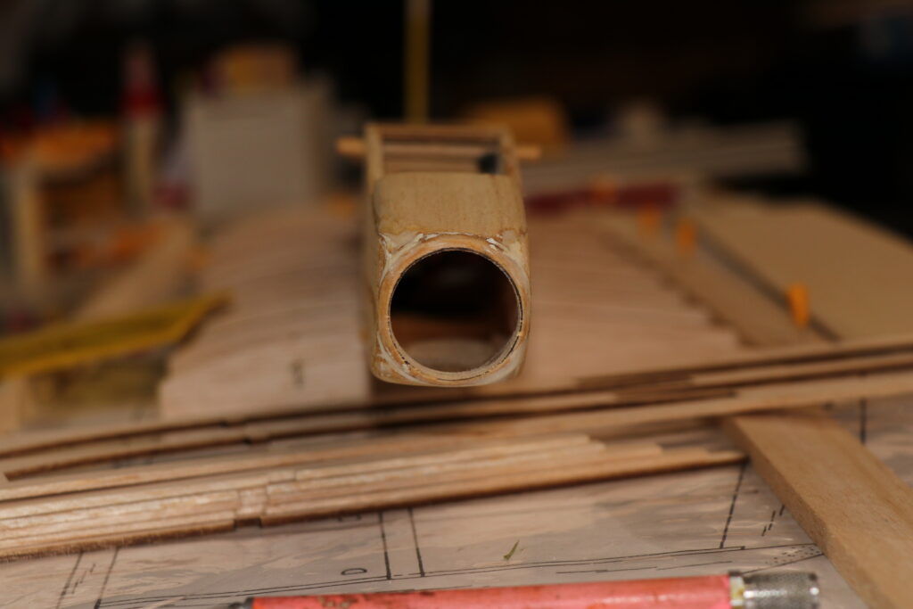
This necessitated removing the original Speed 400 mounting plate, which I did using a combination of rat tail file and Permagrit round sanding stick to the outline of an appropriate metric socket. There is plenty of structure left because the original nose plate was a multi-layer piece of German overkill. It is verruh verruh thick up front, which actually made for a solid nose ring after all the sanding was done.
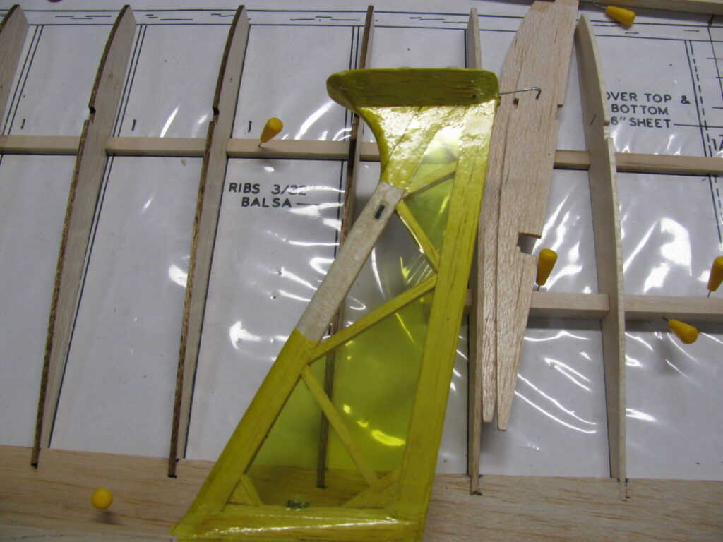
Unfortunately, some hangar rash has also gotten to the Skimmer, some very recently induced: point of fact, I dropped the damned thing on its tail.
You can almost see the crack right at the point where I cut the carbon slot
The only damage to the fin was directly in keeping with the discussion that had been had on RC Groups about how T-Tails tend to be fragile for a variety of reasons.
This is especially true when you are talking about ground loops or anything where the horizontal stab contacts a solid object while the rest of the aircraft is still in motion.
In this case, the leading edge of the fin is a balsa composite of 1/16″ strips which I did so that I could run the elevator actuation cable up through the hollow. In hindsight, I really should have either buried some 1/16 basswood or carbon fiber in the middle instead of more balsa.
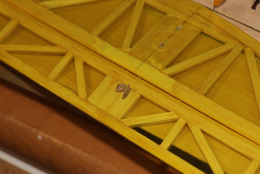
It’s a one-off, so not a huge engineering concern. I wrestled with splicing in basswood or carbon on the front and rear of the leading assembly, but decided in the end to simply use thin CyA and a little carbon fiber bridge across the crack for reinforcement. I also put a few slits along the grain on the opposite side where the balsa had yielded and wicked CyA into those as well to stiffen up the bent region.
Just a teeny, tinsy bit of carbon
In the photo above, you can also see the “L” I put into the Sullivan cable for going through the elevator push rod. The reason for that is:
That didn’t work so well
When I dropped the fuselage on its tail, the 1/16″ ply control horn I custom-made disintegrated.
After doing some checking on-line, I acquired some 0.060 stryene sheet to run in the laser printer to make a new control horn. I hate to say it, but I think I’m going to trust that to be a bit more durable in this situation.
The proposed energy source
The other big decision was to not to try and shoehorn in a ridiculous battery pack and to go with something easily available, so I grabbed an E-Flite 800 mAh pack. I think the key to getting better performance for this plane is not to try and stuff some ridiculously high-powered system in it. Rather, I want to take advantage of the improved efficiencies of the brushless/LiPo combination to improve the handling and sink rate of the plane.
The only piece of hardware left that I need to complete the package is the folding prop/spinner assembly. I have ordered a 36 mm spinner assembly from Esprit Tech, who seem to be the main portal for quality German sailplane stuff to the USA now. I also picked up a couple of extra prop sets to try and see what kind of current draw they give me.
More on this when I get the styrene sheet and spinner/props in.
Yesterday, I had enough of being stuck in and around the Garrison Lodge and took it upon myself to head into town to get rid of some fluorescent bulbs, old NiCad batteries, hit Menards for some sundries, and finally the storage unit for…something.
(Brief aside: I kind of forgot why I needed to go to the storage unit and ended up looking around at all the various crap still stuck there pending disposal or re-homing and wondering why I had felt the need to be there. I ended up grabbing my Sig Rascal kit (because I plan on going to the Sig fly-in in September and the Rascal seems appropriate) and throwing it in the car. Then I drove away kind of happy but befuddled. However, once clear of south Lafayette and trundling my way Northward for gas, I remembered that I had wanted to grab the universal repair grills for my charcoal grill that had been squirreled away in the unit since our 2018 move. Nuts! I’d blame getting older, but I’ve always kind of been like this.)
Which brings us back to the story
The reason I was headed North involved the aforementioned fluorescent bulbs for disposal. The Batteries Plus store where I have been taking my tubes for disposal as they die and are replaced with LEDs is no longer accepting unboxed bulbs.
The proprietor noted that a facility on North 9th street was accepting unboxed fluorescent bulbs for disposal. So, after hitting Sam’s Club for go-juice, I trundled northward to see if the site was where I remembered it being.
By lucky mistake, I ended up turning onto Schuyler Avenue (pronounced Sky-ler for the non-Lafayette folks out there), which may be attributable to age or to the guiding finger of the almighty, because I certainly did not want to go that way originally. However, since turning around would be a pain, I chose to follow possible divine guidance and catch 9th south of the railway viaduct and then go north.
What this did was set me up perfectly to visit the Lafayette Cloud Jockeys field. This realization led me to long for the sound of models alive in the air.
After wandering back along the cinder extension road to the field and passing by a couple of club members taking their evening leave, I found to my delight that several pilots were still there, thrashing the evening air with their electric planes.
I parked the car and paused for a while under the field shelter, listening to the sounds of props cutting through the light breeze and watching my fellow hobbyists enjoy their moment. However, the population of barn sparrows who had residence in the rafters of the shelter took exception with my presence so near their babies, so I relocated out to a picnic table between the shelter and the flight line.
After a bit, a couple of club members stopped by to chat and introduce themselves. Unfortunately, I did not write down names, but I am sure I will get to know them better as I get more involved with the club. We had a good mini-sandbagging session, discussing the current state of the hobby, technology, and the recently announced end of the Toledo Show.
Which leads me to the subject of this post
Several topics came up as we spoke that made me realize that I have been too far out of touch with the hobby in general and the community of modelers in particular.
First off, the initial gentleman who welcomed me responded to my observation that all the aircraft present were electric by noting that model airplane fuel is becoming more and more expensive – primarily due to the lack of availability of nitromethane which is no longer produced domestically and must now be imported.
That shocked me. I had no idea that one of the primary additives to methanol that enables higher performance non-gas engines had become a problem. Then I thought about how the availability of standard glow engines has truncated over the last decade. For example, the fact that Cox engines are no longer being manufactured is something I never could have imagined in 2000, yet here we are with a single outfit providing a few new motors made from new-0ld stock until that dries up. Smaller motors, the 1/2-A class especially, are all but extinct. The sources for new larger motors is effectively a 2-horse show with O.S. and whatever Chinese manufactory that Horizon buys theirs from.
Electrics are the new normal, now. This is actually fine from my perspective, as I have always like not getting my models oily. That said, the cost/benefit curve for larger models does not exactly favor electrics, so having a glow option for larger models is not a bad thing.
A gentleman who had been piloting a flying wing around the field stopped by the picnic table and joined in. The model was a folded-foamboard job and we talked about performance, structure, motor, prop, and all the other joys and challenges he had faced in making the model a reliable flyer.
As we talked, he kept referring to the “flight test crew” since they were apparently the original designers of this particular wing. Eventually I asked who the flight test crew were, expecting that they were a group within the club.
It turns out that this is actually a group of folks with a Youtube channel and an on-line shop: flitetest.com
They do all sorts of absurb, clownish challenges as well as more serious builds and monetize the Youtube model with their work. After visiting their site and seeing their logo, I realized that my Night Radian was actually tied to Flite Test for marketing.
This put me in mind immediately of Pat Mattes back in Fort Wayne and his never ending pursuit of fast-building aeronautical weirdness on the cheap.
What was really interesting was how the members of the Cloud Jockeys had taken on some issues with the original Flite Test design and started leveraging current additive manufacturing techniques to get to where they wanted to go. The wing owner had already come up with a 3D printed structure that he intended to try to improve the stiffness of the wings.
After wrapping things up at the field, I wandered off to Olive Garden and tried to digest what I had heard and learned. It escaped me while I was there, so I headed home.
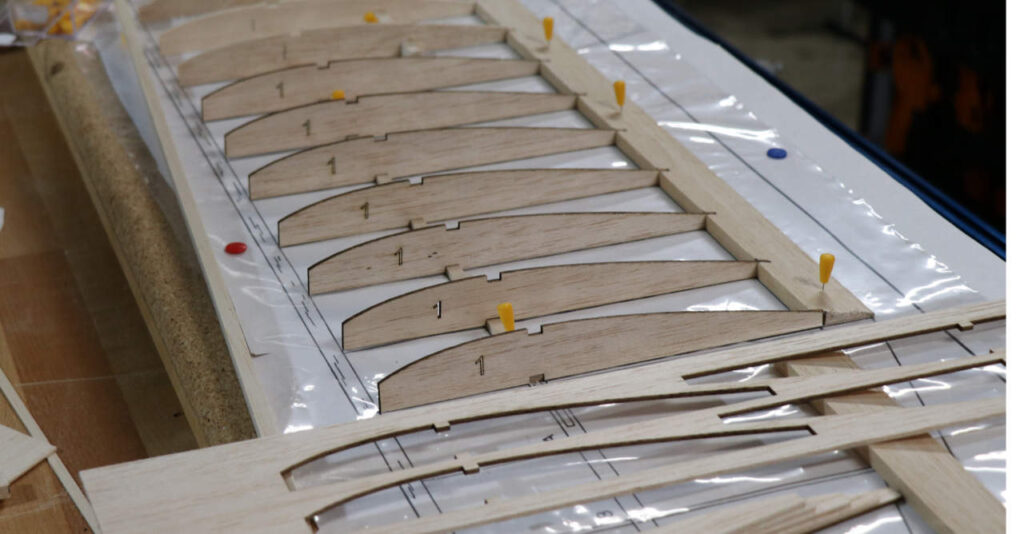
I had one other goal yesterday: I was, come hell or high water, going to cut my Miss Priss ribs on the laser.
An attempt on this had been made previously after a serious effort to align, clean, and check the laser machine. There had been success but, due to a combination of forgetting to set the focal length height and a CAD error, I ended up with ribs that were not cleanly cut and were too small to boot.
The CAD error corrected and my height adjustment error realized, I was primed for success.
Then I shorted out the laser tube wire to the chassis, “fixed” it, shorted out to the chassis again, then “REALLY FIXED” it (i.e. cut wire back to clean, solder joint, double-wrap in tape, then secure to the glass laser tube itself because if you can ground through GLASS then there’s bugger all that will stop you in my shop).
Finally – FINALLY – the program ran with a working laser. When I picture up the balsa carrier after the run, the ribs stayed right on the platen head where I wanted them.
SUCCESS!
I made minor adjustments to the speed of the engraving pass and the power of the cutting pass and re-ran it for another 4 ribs.
SUCCESS!
At this point, it is tempting to wander into the tech details of what I want to improve on the laser and how for kit use you want the parts to stay in the carrier by including tabs and such.
However, at this time, what is germane to the discussion is the fact that I went home and fired up (almost literally) a laser machine, which sits right next to a 10-year old CNC router, to cut parts for a 50 year old airplane design cadged from an online website dedicated to keeping those designs available, both as history and as potential projects. All this after discussing design details of another plane while looking at additive printed concept parts for that plane which were locally made. The plane itself was conceived by a group of RC nuts who have a Youtube channel that is now a major influence in the hobby, even as the old guard of influence, the Toledo Show, finally succumbed to the rocks along the shore of change.
Now, do not fret. This is not going to be some maudlin “everything is changing and I’m so sad” kind of post.
I do have worries, as do many of us in the hobby. Chief among these is how, thanks to the pestiferous commercial Drone lobby and clueless morons who think flying drones in front of any full size aircraft is funny and exciting, the FAA is now doing its best to kill RC modeling with the same soul and wallet choking Totalitarian bureaucratic efficiency that they have used to effectively drive private non-commercial aviation into near extinction.
That aside, this post isn’t about fearing change. It is about how change is both inevitable and good. Sure, some things we are used to are lost, but there is always New Cheese.
Okay, example one: Tower croaked and a bunch of Great Planes kits that are core to a certain population of modelers went away forever. Setting aside the fact that planes come and go like the latest New Dork fashion trends and that Tower was not exactly a paragon of keeping older kits available outside of certain major sellers, this is an indicator of change, not a tolling of the apocalyptic bell for RC modeling.
Building is not really dead. It has changed in priority.
RTF models are pre-eminent and not just a fall back when your hanger is empty due to flying season casualties.
Electric models are now the norm, not the exception. Lots of modelers do not really understand all of the intricacies of them, but that’s okay. A lot of modelers don’t even know how a servo really works, either. The thing is, the infrastructure has changed to the point that you don’t have to be an expert to fly electric anymore.
Manufacturing has changed. It used to be that some rather significant tooling was required to make kits. Airtronics used industrial sanding machinery to make their sailplane ribs. Die-crushing requires a not common piece of industrial press equipment as well as a die maker to create and maintain. Vacuum forming on a production scale is an entirely different exercise than on a home-made rig in your garage.
That has changed in certain key areas.
For example, laser cutting of work parts is now the norm. Die cutting can be used on some ply parts, but now there’s even CNC routers for making cuts in heavier materials. There’s also CNC foam cutting, if you fancy that sort of thing, and the entry for all of these technologies is not that far up the monetary scale.
If you are an industrial concern where cost is everything when it comes to emptying modeler wallets, there’s an entire city in China dedicated to ripping off designs and custom building volume model airplanes for the entire globe for pennies on the slave-labor dollar.
Things have changed significantly since 2011 and even more so that 1998. I saw a post in RC Groups where someone talked about not building an EPP plane “using the old school strapping tape” approach.
Whoops. Guess I need to take a look at how the Push-E Cat is covered. I was already going to undo a lot of that kind of reinforcement anyway, but that statement seems to be a canary saying that using any such approach is seriously retrograde.
Change needs to happen. What you used to do may not even be feasible anymore due to changes in supply.
I think one of the more telling things is how expensive what kits are available now have become. Kits I remember being in the $30 or $40 range, like the Balsa USA Swizzle Stik are now over $100. That’s absolutely nuts! Fancier kits are even more.
How that came to be has to do with the dynamics of scarcity in a changing market. See, when a market changes, products aligned with the original market that are in pipelines to meet that market demand, tend to end up with supply surplus for a time. This has a real-life example that immediately comes to mind where Tower was DUMPING Sailaire kits for over a year at cut rate prices.
What then happens is that the manufacturer either ceases production entirely or cuts way, way back to align with the new demand. Thus, if the product has a durable shelf life, which balsa kits can have, you end up with a downward line of availability which drives an upward line of price. Since it is likely that, if a manufacturer seeks to keep a kit in production, they will shift to more flexible manufacture methods that require less expensive tooling, smaller shop footprint, and more production flexibility, the cost per component in the kit will rise.
Add to that the necessity to justify keeping a kit available by providing sufficient profit margin (lights have to be kept on, air conditioners running, staff paid, after all) and you get really expensive kits.
Two outcomes from this: 1) More people just buy Chinese RTFs because, frankly, they’re now way cheaper or 2) People start to say, “Hey, if I have plans, maybe I can build one of these myself” if they really want a particular model.
More likely, people start to say, “I really used to like model “X”, but it’s kind of dated now and I want to do YZ in addition to the old school stuff. I wonder what’s out there?” And then they sniff around the web and find free plans for something they like or a garage-operation plane kit that’s close enough, or whatever.
The key is that things have changed. They’re always changing. But, oddly, a lot of the old school still remains enmeshed and ingrained in the new.
That’s what the picture at the top of the post signifies. If you check it out, you can see my new ribs from last night lined up closest to the front. In the back, there are ribs made the old-school way: I cut out templates, glued them to the top piece of balsa with 3M-77, then made a stack of blanks using double-sided tape, after which I used a band saw and a sander to shape to the template line.
New school laser ribs with old school template ribs. Two paths to the same point using alternate, equally valid approaches.
That’s where modeling is now and, frankly, has always been. The new keeps happening but it does not completely invalidate the old. It builds upon it.
There’s always a way back to flying glow motor models. It just becomes more cumbersome because the nominal center of the source of supply has shifted to electric. You can still build and fly from a kit. It’s just more expensive. You can still build from plans. That’s actually easier now that you can download almost anything from classic times as well as new designs that are being freely offered. Even then, you can still go the traditional route of building printed plans and starting there.
And now there’s quads. And Hexapods. And FPV. And so much more that keeps adding and adding to the different directions you can take your interests.
So, even though there’s a lot of old-school that’s fallen out of favor, the new school hasn’t completely eclipsed the value that’s still there. I think that the true reality is that we are always blending New School and Old School, trying to leverage past experience with new ideas and opportunities.
That gives me hope for the future of the hobby. It really does.
The purpose of this post is to copy over the previous posts from RCGroups that I have made on on the Push-E Cat V5 design effort to my own blog.
This is part of my effort to add meaningful content to this blog.
First Post, December 30 2018 Push-E Cat V5
I wrestled a bit with how to share on this between doing a forum post set or doing the blog thing. In the end, I think that doing the forum will be better overall to share and discuss with everyone.
Once upon a time, there was the Push-E Cat V4, which was produced by Polecat Aeroplane Works with permission from me. They made some improvements to the old V3 design that were welcome and implemented bell-type brushless motors, which was a huge leap forward. They also did CNC everything, which was cool, too, but has a sizable learning curve.
Then they fell on hard times, what with Denny’s knee issues and infections and whatnot. So I took the Push-E Cat back, but then never did anything much other than to do a single V5 prototype. Reason for that has to do with being laid-off at the time and feeling pretty horrible about myself. When you’re depressed, even the obvious paths out are hard to take.
Now it’s 2018 and I wanted to make a kit for a friend’s kid. I had started down this road in 2017, but then the friend said that his kid wasn’t ready yet. Then a lot of moving happened. The end result is that I am now in a much better place to work on models than I was a year ago. Additionally, I’m planning to improve my business by implementing strategies to get more HVAC calls using SEO as I finish out my free-standing shop that currently doesn’t have any electricity, insulation, or HVAC.
One of the challenges I faced back in 2010 was that I tried to match Denny’s CNC capability, at least in terms of the fuselage, by shifting to a Phlatprinter III. The Phlatprinter is a really cool tool, but I was trying to use it in a way that didn’t mesh with the machine’s purpose and capability. To do what I wanted to do originally, I would have had to use a flatbed 3-axis router table with a 24×36 working area. Cycling the material back and forth multiple times through the Phlatprinter inevitably resulted in material drift along the feed axis as multiple passes were made to “mill” features.
What I’ve decided is that the goal is to make some kits to share regardless of process, and that’s let me re-create the processes and capabilities I had before I wandered down the CNC hole. I’ll continue to mess with CNC, but I’m not going to let the lack of CNC keep me from driving the design forward.
This also begs the question of why I even bother. The hobby has moved on, hasn’t it? I honestly wonder if anyone would even be interested in an EPP kit that you have to build rather than a molded Chinese toy that you can shake out of a box and take flying in 20 minutes, plus buy all the service parts you could possibly need for at least a year until they moved on to the next big cash cow.
The answer is, I’m no longer trying to live off this. This is officially a hobby “business” which means that it’s a hobby first and that any money I might make gets reported as “hobby income” on my tax forms. I’ll put kits up for sale as I make them, when I feel like it, and use any cash I get back to buy CNC toys and design other planes and kits to share. If no one builds any of my designs, I’ll be disappointed, but then that’s all right. At least I’ll have fun making them.
After I get the V5 polished up and finished, I’m going to finally do the Hand-Cat as a discus-launch. After that, I’m going to do an omage EPP version of the Craft-Air Piece ‘O Cake. After that, I want to do 1.5m and 2m ALES gliders. Then there’s the Cabin Foamie, etc. A never ending stream of things to make and share.
All while doing things to experiment with and extend the tech of home-cut EPP model airplanes.
With regards to the V5, I leared a few things and came up with some principles. One of the things I learned was that the kraft-paper reinforcement works, but it’s heavy and kind of complicated to do. So, I shifted over to carbon reinforcement for the tail boom.
Along with that is the problem of working to make the plane as easy to build as possible while designing in robustness. It’s this weird balancing act where you have to imagine what exactly you can expect from a builder and how much you can ask or push for to make the plane perform better. Bizarre stuff and something that I fear can never be 100% effective.
What’s worse is that you cannot reliable design for a particular motor anymore. I still have a few of the old Bell-type motors that Denny was packaging with his V4’s, but I don’t think you can get them anymore. They were wonderfully simple to install and use. I imagine it has to do with the competitiveness in the brushless market, but it make it harder to stabilize the design of the motor mount. I’ll probably have to just provide a centerline and prop clearance dimensions on the plan and give some hints and let people sort it out on their own if they use something other than what I’ve used in the shop.
I’m going to start out with a single-piece wing with glued in joiners at first. Unlike the original PEC, the new, longer tips are really not suited for just being taped on. I have a path to removable tips, but I will make that an option only after I get the parts made and try them out myself fist.
One thing I can do relatively quickly is the -A option for an aileron wing. That wing design was basically confirmed on my Twin-Cat prototype and works fine.
So, more to come as I work through. I hope some folks will chime in and discuss things with me here as I plow forward. It’s the best kind of collaboration to discuss and debate design trade-offs and help make a better plane.
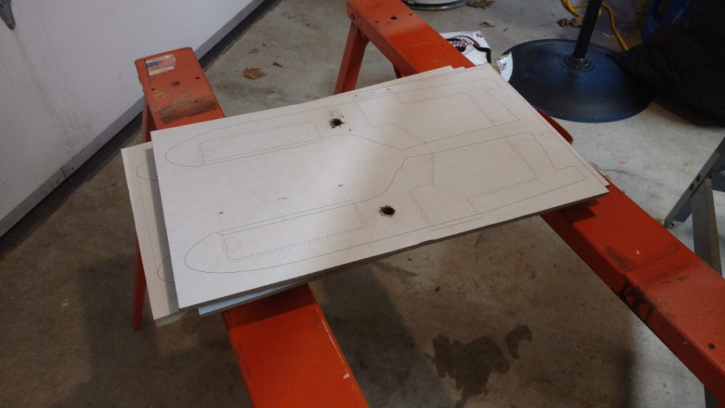
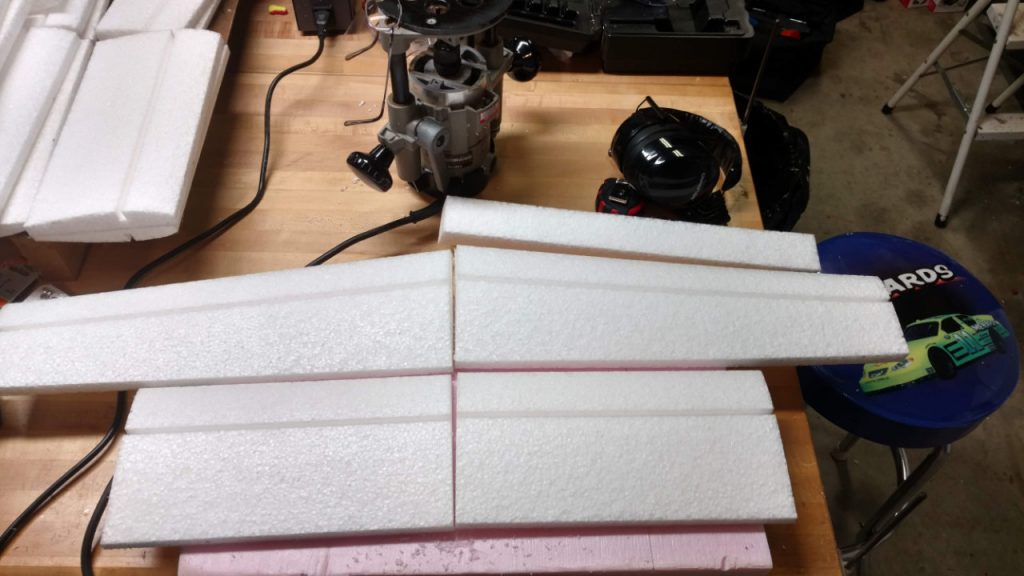
Starting on router templates
Second Post, January 1, 2019, PEC V5 progress, 01/01/2019
Finished building new router template boards for cleaning out the internal cavities in the fuselage and cutting the servo pocket through-holes.
How to make holes in EPPPost-router fuselage halvesRouters with guides
Only thing missing from the foam set at this point is a canopy.
This has been an adventure of finding old tools, filling in gaps in tools by trips to Menards, and stepping back and thinking things through in terms of not using CNC to cut the parts as originally envisaged.
I already have some wood parts that were cut on the Phlatprinter for the motor mounts. When those run out, though, I’ll probably contract with a laser cutter to make more. Not sure about the stabilizer platforms. Have to look in the wood part bin out in the unfinished shop.
My manual cut parts (band saw) require layout templates. The old CalComp printer that’s followed me back and forth across Indiana and Ohio finally gave up the ghost. My one trip to FedEx/Kinkos to print on their HP was a clear indication of how inconvenient that’s going to be. So, I have a new 24″ HP printer on the way. It won’t only be used for models. I have other projects for the house and such that will make easy use of a handy large-format printer.
Next step is to finish up the canopy template and get those cut and sized. Once the new printer is here, I’ll get the taper template for the tail boom completed.
Work on the instructions needs to be done, as well. I’ll probably work on that while waiting for the printer and after finishing the canopies.
First complete PEC V5 cores since 2011
Third Post, January 5, 2019, PEC V5 progress, 01/05/2019
Received my new HP 24″ printer yesterday and spent the evening assembling and setting it up. First thing I printed was a new fuselage profile, as I had discovered that what was currently in CAD was not corresponding to the template I was using.
The old CalComp printer served me well, but it is a 20th century device. The new HP has all the current technology bells and whistles and even cuts the sheets for me. I will have to recycle the old CalComp with full honors. If anyone thinks they can fix the paper feed connection between the stepper motor and the rollers, they’re welcome to the printer for free. I will note that the only driver software I’ve been able to find is from Australia and costs $200. Maybe someone’s got more printer mojo than I do and can do it a different way. (Need to check and see if the Aussie driver will work with the new HP and if there’s a “custom paper” option in it. The HP driver doesn’t seem to like the idea of me defining my own print lengths even on a continuous roll.)
The big clue that something was wrong with my fuselage template from 2010 was the fact that the canopy printed from the current CAD didn’t fit. After dinking around a bit to verify dimensions between the real and virtual worlds, it became obvious that I had, sometime in the interim, revised the curvature of the nose.
This really isn’t too surprising. The V5 has a longer schnoz in order to balance with the lighter brushless motors. I just hadn’t remembered doing the iteration between the template that built my pilot model and now.
In any case, I was able to get the new template made and adjust the three fuselages I have already cut to match it. Fortunately, the old template was proud on one side so I could rework things to fix it.
I’m working through converting the V5 design from the original CNC router fuselage to the current manual cut fuselage. My intention originally was to have all the internal slots and everything cut on the CNC. This was driven by the Phlatprinter paradigm and using 1″ foam to feed the beast, as it were.
Now, though, I’m back to the old V3a/V4 way of doing things with the band saw and router templates. It works well enough for what it is, but putting in all the smaller, more precise slots for the carbon inserts and vertical fin is going to be more challenging.
To that end, I picked up a plunge route base for my Dremel that I use for router work. The old base is not square with the world and only good for gross cuts. I think I can do the lighter internal cuts on the tail boom and front fuselage much better with a more substantial and precise base.
I really wish I could lay hands on a die cutting press to make the tail pieces. Coroplast is much happier in a die-cut environment rather than a band saw one. The edges can weld together in the stack as you cut, which is a pain, not to mention getting the double-stick tape off.
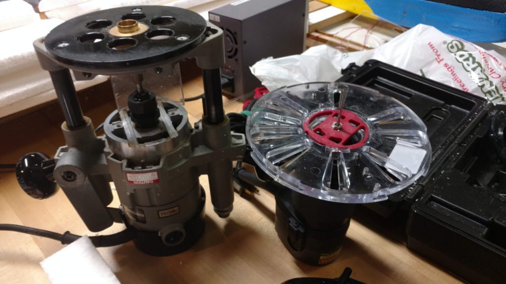
Eventually, I want to get my shop set up with a laser-cutter for doing balsa and play, a larger bed 3-axis CNC router, and a CNC foam cutter. The Phlatprinter probably still works, but I haven’t set it up yet and tested it. I think the original incarnation with the flexible polisher from Harbor Freight is probably the best way to use the thing. I tried setting it up with a Bosch router, but the weight was probably not the best for the system.
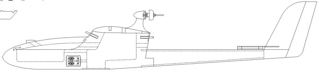
Thought I’d throw up a couple of screen shots showing the difference between the V0-V4 series and V5 fuselages. The V5 really is sleeker. I’m also going to provide direction and options for tapering both the rear of the cabin and the tail boom. The pilot proved that the Cat gets a lot slicker with just a little aerodynamic “adjustment”.
V0 side profileV5 side profile
Fourth Post, January 11, 2019, Obsolescence and motor choice
So, I was poking around on “da interwebs” and confirmed what I already knew, which is that the Towerpro 2800 motors are now obsolete relics.
This led to additional poking around on various sites to see what actually is available. Turns out there are various valid options that won’t break the weight bank.
That said, I now need to design 3 different mounts for the various options, each with some level of adjustment for the variety of choices people have.
I’m still partial to Bell type motors myself, but I certainly don’t want to cut out people’s choices.
Motor pictures tomorrow.
Fifth Post, January 14, 2019, PEC V5 progress, 1/14/2019
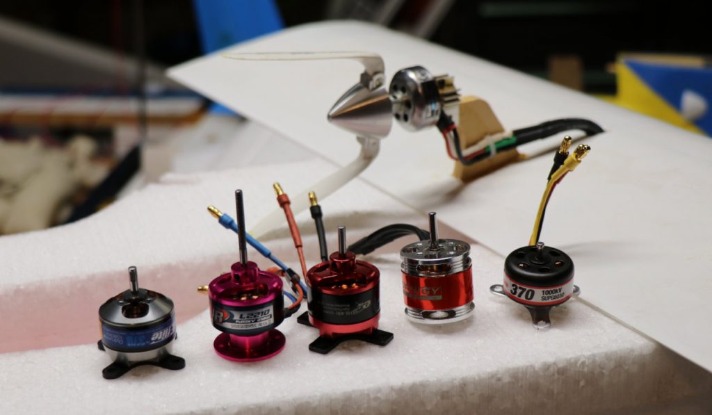
Okay, so I promised some more pictures regarding motors.
First picture is of a collection of 28 mm outrunners I had in my inventory with the trusty Towerpro 2800 hanging out in the background on V5 prototype 1. From left to right there’s an Eflite Park 370, a Turnigy Air L2210, an E-RC BL400, some Turnigy motor I thought looked cool so I bought 3 of them but I have no idea what the KvA or power limit is, and a (haha) Supertigre 370.
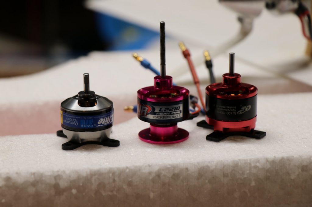
After checking around a bit, the only ones that are still available are shown in the next picture: The Eflite, the Turnigy L2210, and the E-RC BL400. So, those are going to be my basis for design for the V5 motor pylon design.
In the process of sniffing around and using my calipers, I discovered a couple of interesting things. First, the L2210 looks to be the direct descendent of the Towerpro. The assembly length is identical. The L2210 is actually 2 mm smaller in diameter than the Towerpro, but both are 1400 KvA motors.
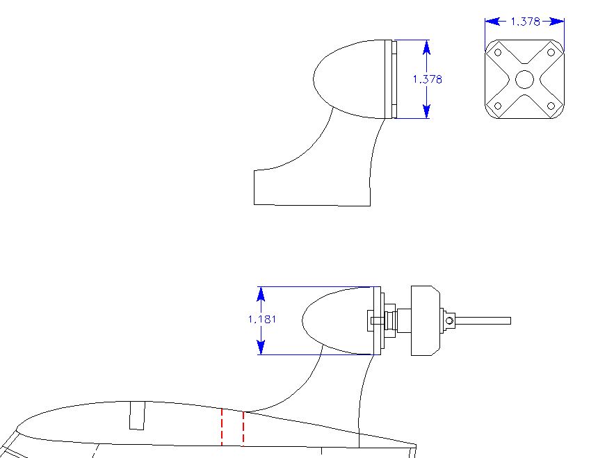
Second, the E-RC with its cruciform mount attached is almost exactly the same installed length as the L2210. The Eflight motor is a bit shorter, but if I design for the longer, common length, then the Eflite could be fitted with spacers or a block.
The Eflite motor does have a more refined cruciform mount, though. Rounded the ends actually makes it more compact for installation. Of course, fixing that for the BL-400 just requires the judicious use of a file or a Dremel, but it’s a nice, professional touch regardless.
In any case, picture three is a snapshot of my design screen showing the two different mounting pylons. I messed with having one pylon for both, but it ends up making the “egg” bigger for the Turnigy install which looked weird.
The big difference between the L2210 and the Towerpro is that the Towerpro’s radial mount diameter was significantly smaller than the diameter of the motor itself. The L2210 mount is the same diameter (28 mm) as the motor. Just enough difference that I wasn’t able to use the original Towerpro mounting pylon, which sucks because I have a shelf bin full of the things after running a cut program on the old Phlatprinter many moons ago.
Next step is to do some solid modeling in 3-space and see what both the bell-type mount for the L2210 and the transitional rectangle for the other outrunners will end up looking like.
Found in the motor boxLikely suspectsInitial motor mount concepts
Sixth Post, February 10, 2019, Progress on Motor Mounts via Phlatprinter
So, haven’t updated for a while, but project continues.
Here’s what happened:
I designed the new motor pylons for currently available motors. I then printed out some templates, glued them to MDF board, and fired up my old reliable Delta bandsaw.
The results were…rough. Okay, just cutting the templates reminded me why using a bandsaw on foam is okay but wood parts really aren’t amenable to that process, at least not enough for me since my eyes are going and I have way too much caffeine in my system.
I put things aside for a night to think about it. Somehow between that bandsaw session and waking up the next morning, I had decided: I would get my old Phlatprinter running again and let the machine do it.
For cognitive reference, had I stopped to notice, this is right up there with, “I shall summon a small CNC demon to do my handiwork as soon as I find a gypsy with a goat.”
In any case, I have reaffirmed that my impression that CNC is very much its own hobby that swallows time at a geometric rate depending on how much you want out of it. I knew it before. I have re-learned it again.
I am now much more appreciative of what Mark and Trish accomplished with the Phlatprinter machines. Now that I’ve been around the block a bit more, I recognize how great their accuracy actually is for what level of investment was involved.
That said, I still had to contact CNC-USB and figure out why I was having trouble talking to the machine. Once they got me straightened out, and once I re-learned how to calibrate the thing, and once I figured out the archane art of using SketchuCAM to made GCODE files, it’s actually working right and reliably. Which makes me wonder why younger Darwin had so much trouble coming out of his navel-gazing and realizing what he could do with the tool.
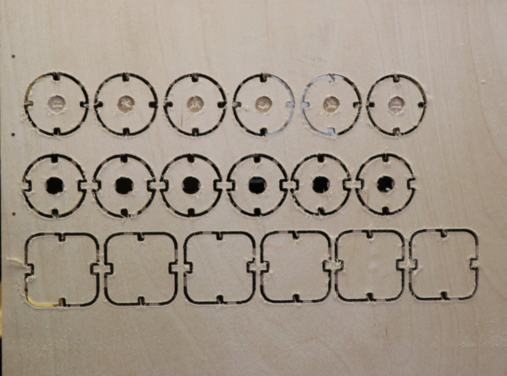
Thus, I have now finished Phlatprinter-friendly versions of both the Radial and Bulkhead style motor mounts.
Here’s a link to a video of the Phlatprinter doing its thing on the pylons:
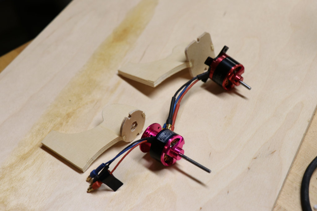
First fit up with intended motors for comparisonThrust plates as cut on the Phlatprinter
Seventh Post, February 12, 2019, Closing in on finishing the radial mount
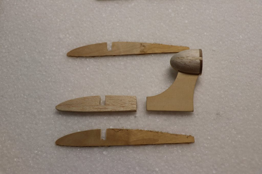
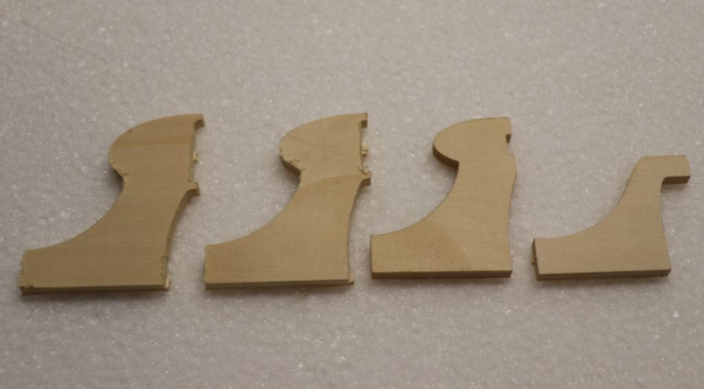
Stayed up late last night after running the balsa side-bolsters on the Phlatprinter and finished up the radial mount “egg”.
Did some digging in my “box of stock” that I’d cut previously and found enough bits to finish at least one new motor mount.
Pictures below show a) the new radial mount along with the bits to finish the center section “root rib” and b) a comparison of mounts, newest on the left, oldest on the right. Center line of the new mounts have been adjusted to provide 0.5 inch clearance to the tail boom for 8 inch props. Old mounts were a wee bit closer to the boom than I really liked.
Should probably have the radial mount root rib assembly done tomorrow. Still looking for the original CNC cut files for the extra parts. May have to re-create them.
Eighth Post, February 18, 2019
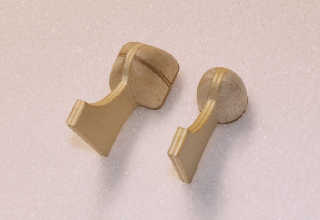
Finished up the new side bolsters for the cruciform mount and assembled that section. Whittling the balsa fill to shape and sanding it into submission is definitely more challenging than for the radial mount.
Point of reference, the side bolsters on the cruciform are 3.0 mm plywood. (3.0 is not 1/8″, Midwest. Quit lying on your labels. Screws with my tolerance stack up.) I used ply because I really had to be careful with the balsa side bolsters on the radial mount to make sure I only cut and sanded up to the edge to maintain the curvature.
That said, next time I’m using lite-ply. It’s still tougher than balsa and I have better things to use plywood for (like the press plates).
The cruciform mount is noticeably heavier than the radial, which should have been obvious before I made it, but I got in a hurry. In the instructions, I’m going to suggest cutting away some of the inner corners of the fill blocks to lighten them while still providing enough wood for shaping.
Can be done for the radial, too, but the cruciform will need that whereas it’s just “nice” for the radial.
I’ve pretty much decided that the bog-stock V5 will be based off the bell motor. Having a cruciform option is okay, but it’s something that a customer will have to want to have for whatever reason. The plane will be better for its intended use with the bell motor.
That vaguely segues into a discussion of design intent and avoiding line to line designing that I’ve been thinking about.
The Push-E Cat has a purpose to its design, which is to be a rugged and forgiving trainer and all round fun plane. It’s not a pylon racer or an ALES competition model. It goes up, flies for a long time, and bounces when it smacks terra firma inadvertently. The fact that it actually does glide really well is a bonus. What matters most are gentle flight characteristics, ease of assembly, ease of maintenance, and overall cast-iron durability.
The Ease of Assembly bit is one that takes more work. EPP models can very quickly become challenging because the base material is not particularly fond of being glued with epoxy or CyA. Oh, it will work. But when you smack into the very large immovable round object we all stand on, regular modeling glues don’t have sufficient “give” and you end up ripping pieces out of the parent foam rather dramatically.
This ends up translating into added complexity as you specify the appropriate adhesive for each sub-task on an airplane. The PEC, for example, still can use standard glues for assembling the motor mount and dowel carriers. However, to glue hard wooden bits to the foam itself, you need to use polyurethanes like Gorilla Glue and Pro-Bond. For carbon fiber stays, the best option is E6800 or some other Goop derivative. Plus the foam has to be prepped for covering because regular tapes or iron-ons just can’t stick to bare EPP. At that point, it becomes something of a free-for-all with everything from Elmer’s Glue thinned with water to 3M77 or 3M90 and even DAP Weldwood, both the stinky and the water-based kind. I honestly don’t know which is best and I’ve tried them all.
Frustrating. And then you have to try and put that into instructions that someone who’s never built a model can understand and has no idea why they need 3 or 4 adhesives instead of just one.
Ah, for the days of Ambroid. Blarg.
The reason I’ve wandered into that is that if you’re going to try and take complexity out of something for the end user, you have to drive necessary complexity out of sight and into the base design. Things like making sure your notches and spacing are set up to deal with the fact that 3.0 mm is not 1/8″ or the fact that real materials vary and if you try to design something without any tolerance between the parts (i.e. “line to line”) then things won’t fit right out of the box without some rather particular modifications by the end user with a hobby knife and sanding block.
Which makes a model harder to build. Which can discourage someone who is just starting. Which causes the primary function of the product to remain unachieved.
So, the PEC V5 has two areas that I am significantly concerned about in terms of ease of assembly: 1) The motor mount and 2) The wing joiners.
The motor mount I believe I have muscled through and can finish up the design work on enough to generate the production CNC programs. That’s why I lingered on it so long.
The wing joiners, well, I haven’t really gotten that sorted yet.
I’d love to have removable wing tip for two important reasons: 1) transport-ability and 2) ease of maintenance/replacement.
The issue is that adding removable tips to a design can be a major complication to building. It’s far easier to drop in a ply joiner and call it good than it is to engineer and build a properly aligned and durable joiner system.
I think I have an idea of how to do it, but it will require some investment on my part not just of design but of tooling and sourcing to make it happen. This is an example of driving the complexity away from the end user and into the baliwick of the design itself.
Choices like that are part of any engineering design: “Should we do this?” “Does it add too much cost?” “Will the customer be able to complete that task?” “Do we need to control the tolerances so that the product will function correctly?” “Is letting the customer do it too much risk?”
The answers to those questions go back to the intended purpose of the design and the expected capabilities of the target customer base. And every design feature has to be looked at going back to the original purpose of the project.
Anyway, just the muttered musings of an aging career design engineer as plods his way to actually making a model reasonable for others to build and enjoy.
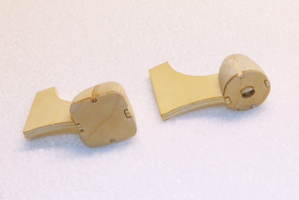
A complete radial mount setMount design progression, newer on the left, older on the right
Ninth Post, March 12, 2019, Cruciform versus Radial Mount and Design Considerations
Checking in to let everyone know that the project continues.
I have been elsewise occupied with helping deal with the fallout from the passing of Ray Hays of Skybench Aerotech fame. There are lessons to be learned from this, in addition to simply doing what one can to help a family deal with a mountain of model business/personal modeling possessions.
Since I’ve been reworking the V5 design documentation and rationalizing the design, I have been attempting to bring my experience as a design team lead for a major manufacturer into what I’m doing in terms of documentation. Not that I need the whole corporate kit and caboodle, but there are benefits to having a robust engineering documentation structure to work with.
Ray’s passing drove that lesson home. Frankly, if it wasn’t for the support of the people with engineering backgrounds who did his laser cutting, the kit documentation would be functionally illegible, and that has a direct impact on the value his family can obtain from the sale of the business and kit rights associated with it.
Some folks do get it. Established kit manufacturers definitely get it. But often, less focused more artsy or sales type people don’t really get it. If you don’t properly document a design, it really doesn’t exist, and putting together a product without decent documentation is a nightmare and customer service whirlpool of effort.
Based on that, I’ve been spending some time getting drawing formats sorted out for my CAD system and generating a “design documentation database” which is just a file structure at this point for saving the various required information for each PART of a design as well as the overall assembly models.
For example: A solid model of the part. A drawing of the part with enough dimensions on it to be used to check a physical part to make sure it meets design requirements. The CAD file used to drive the software that generates either CNC router or Laser Cutter tool paths. The actual toolpaths for the parts (if applicable)
For a design you have to provide: A Bill of Material (BOM) that will drive your packaging requirements (and quality control) as well as be included with the instructions so that the customer can verify the contents of a package. Instructions Plans with important dimensional directions and assembly notes Assembly illustration source files (illustrations can be used either in instructions or on plans)
My own part numbering system goes a bit beyond that, as part drawings call out raw material parts that are used to make the part in question (as in, motor mount pylons will refer to a pattern drawing for production, which then refers to the bulk raw material to be used). This is part of how you plan for what raw material you need to have on hand for a run of “X” kits.
The effect of all these considerations is that I have slowed down a bit to make sure I set this up correctly. That way, if I croak, my family won’t be completely in the dark about what all those numbered bins of stuff are for and what value each has inherent in it.
Of course, since I’m not doing the full-on business thing, what it really does is let me keep things organized so I can stay out of my own way and out of trouble.
Press plate facesMount front cross section compare
Tenth Post, May 21, 2019
Checking in to let everyone know that the project continues.
I have been elsewise occupied with helping deal with the fallout from the passing of Ray Hays of Skybench Aerotech fame. There are lessons to be learned from this, in addition to simply doing what one can to help a family deal with a mountain of model business/personal modeling possessions.
Since I’ve been reworking the V5 design documentation and rationalizing the design, I have been attempting to bring my experience as a design team lead for a major manufacturer into what I’m doing in terms of documentation. Not that I need the whole corporate kit and caboodle, but there are benefits to having a robust engineering documentation structure to work with.
Ray’s passing drove that lesson home. Frankly, if it wasn’t for the support of the people with engineering backgrounds who did his laser cutting, the kit documentation would be functionally illegible, and that has a direct impact on the value his family can obtain from the sale of the business and kit rights associated with it.
Some folks do get it. Established kit manufacturers definitely get it. But often, less focused more artsy or sales type people don’t really get it. If you don’t properly document a design, it really doesn’t exist, and putting together a product without decent documentation is a nightmare and customer service whirlpool of effort.
Based on that, I’ve been spending some time getting drawing formats sorted out for my CAD system and generating a “design documentation database” which is just a file structure at this point for saving the various required information for each PART of a design as well as the overall assembly models.
For example: A solid model of the part. A drawing of the part with enough dimensions on it to be used to check a physical part to make sure it meets design requirements. The CAD file used to drive the software that generates either CNC router or Laser Cutter tool paths. The actual toolpaths for the parts (if applicable)
For a design you have to provide: A Bill of Material (BOM) that will drive your packaging requirements (and quality control) as well as be included with the instructions so that the customer can verify the contents of a package. Instructiions Plans with important dimensional directions and assembly notes Assembly illustration source files (illustrations can be used either in instructions or on plans)
My own part numbering system goes a bit beyond that, as part drawings call out raw material parts that are used to make the part in question (as in, motor mount pylons will refer to a pattern drawing for production, which then refers to the bulk raw material to be used). This is part of how you plan for what raw material you need to have on hand for a run of “X” kits.
The effect of all these considerations is that I have slowed down a bit to make sure I set this up correctly. That way, if I croak, my family won’t be completely in the dark about what all those numbered bins of stuff are for and what value each has inherent in it.
Of course, since I’m not doing the full-on business thing, what it really does is let me keep things organized so I can stay out of my own way and out of trouble.
Eleventh Post, May 21, 2019
Have burned parts for PEC V5 with new laser cutter.
In other news, found source of shop stench in trap pan of garage refrigerator. Very gross and completely unidentified organic goo.
In all honesty, it has been a strange journey these last nine years.
Back in 2011, I was struggling to reboot Garrison Aerodrome since my job hunting had not yielded any kind of decent opportunity for me to re-enter the world of corporate engineering.
Now, I am a senior engineer at a world famous heavy machinery manufacturer with significant role responsibilities, a team leader in charge for mentoring the next generation of technology and process experts, and bear the suffix of “subject matter expert” in a critical area of core technology in my e-mail signature line.
This has come at the cost of a relocation away from Fort Wayne and the LOFT flying group where I “grew up” in soaring. It has also directly affected the access I have to casual flying since I did not really have time to chase after the local club and find out what kind of opportunities there were.
I started trying to get back into models and model design in 2017 after I found out that one of my managers at work was also a sailplane guy (albeit more into ALES, which is where things have gone now.) Unfortunately, space was a concern, and then my wife decided we were moving to the country.
In 2018, therefore, we ended up buying a 10 acre tract of land in the neighboring county. As part of the deal, I finagled a 14×32 foot “shed” to be designated exclusively for model airplane use. My plan was to finish it out inside and move all of my models, CNC tools, and other required woodworking equipment into it to have my own little airplane cave to do as I please.
It’s gonna be great! (Someday)
It is now 2020 and the shed is full of mostly airplane stuff, completely unorganized, and is also home to the fallout from Ray Hayes passing.
What work I am doing on airplanes is based, once again, out of the attached garage of our house. I have added a Laser cutter, refurbished my Phlatprinter and, true to form, taken on more than I really have time for.
Oh, God. Where to start…
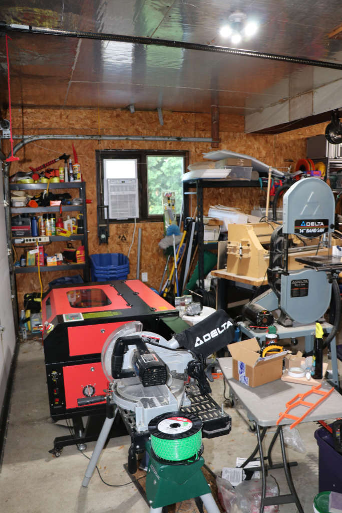
And the shop’s a wreck. Completely unorganized and pain to work in. And my wife still parks her car outside with mine.
On the plus side, I do have air conditioning. Now heat, well, let us see what happens in the Fall.
Yay, air conditioning! But…where do I stand?
I did try and get some Push-E Cat V5 kits put together last year, but I ran into a hiccup trying to find a long-term replacement motor and rational mounting paradigm for what I did find.
Plus writing the instructions. I started and suddenly realized I was writing a book about building EPP models instead of instructions for building a particular EPP model.
I also realized that the market (hobby) is not at the same place it was in 1998-2002. The hobby changes continuously and the addition of LiPo batteries and brushless motors was a sea-change that the V4 Push-E benefited from initially. Then things moved on and that particular hardware combo went obsolescent.
From this, I have concluded that counting on China to provide a reliable long term motor solution is a fool’s game. Thing is, model airplane people can be really stingy and Chinese slave-labor produced model airplane bits are very, very cheap.
In any event, posting to this blog is actually my way of setting and meeting goals that will help me bring the Garrison Aerodrome models back to life as well as drive project-based content for general model community enjoyment.
The truth is that if concrete goals and objectives are not set, things really do tend to not get done. This reality bridges both professional and private life.
The biggest goal revolves around the Push-E Cat. My belief is that there continues to be a need for a truly robust beginner/sport motor sailplane, which can be seen by the various similar platform follow-on designs pumped out by our Asian “friends” for mass consumption in the USA.
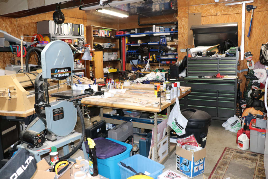
The effort to resurrect the ‘Cat, though, requires me to get other ducks in a row. For example, I need to make an effort to clean and organize my temporary shop environment so that I am safe and not tripping over things – or having to move three projects out of the way to work on one.
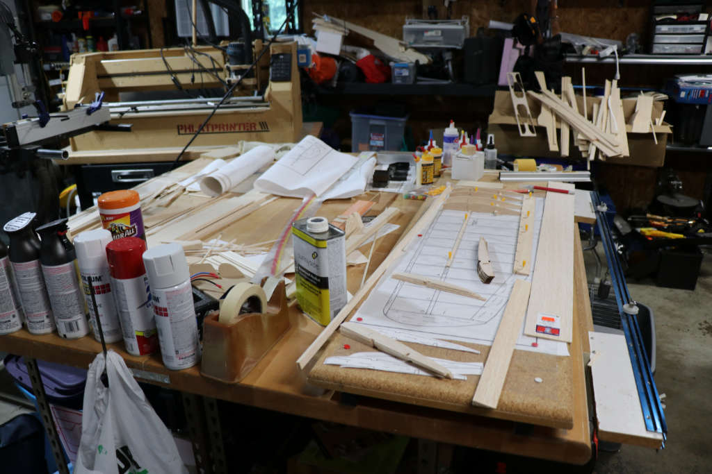
Beyond the Push-E Cat are other things. In the picture of my current build table, you can see bits and pieces of a new build of an old design: a Miss Priss. The reason it is there is because I was bored and let myself take on a new project instead of finishing what was already underway.
A build board surrounded by interrupted projects for the family
Weirdly, though, the Miss Priss fits into a thought pattern for a bigger content delivery for this blog and modelers overall. It is related to many other models, but directly in my mind to the Push-E Cat, the Cox EZBee, the Craft Air Piece ‘O Cake, the Craft Air/Great Planes Butterfly, and the Airtronics Monarch.
Miss Priss bits along with miscellaneous Push-E Parts and a Kestrel kit and much other junk
Every one of those planes is a motorized sailplane of one definition or another, in a fairly easy to build form. The only difference between them and the Push-E Cat is materials and the fact that the Push-E is a pusher prop, obviously. All the rest (except the beer-cooler EZBee) are tractor prop balsa jobs, and that us a-okay. As for the Miss Priss, it was one of the earliest and simplest examples I could find that generally matched the overall concept, so I decided to start there.
There are a few key points here that bind them all together. First is simplicity. All of these models were not huge technological challenges and the EZBee was actually an early RTF. Second is the fact that they all have some form of sailplane wing planform, even the Miss Priss which actually meets the requirements for a LAR sailplane. This is important because this type of planform, as presented, is inherently stable with a mild mannered stall if properly designed, and a speed envelope well within the reaction time of a beginner. None of these planes feature ailerons, either. The three most complex, the Push-E Cat, the Miss Priss, and the Butterfly, add a throttle function. That’s it.
The other key factor is fun. I have not flown the Miss Priss yet, but I expect an experience similar to the Push-E Cat and my occasionally-lamented deceased Piece ‘O Cake: gentle, relaxing, and encouraging to fly. A model that eases you into testing its limits with each successful landing and the expectation that you will be right back up again as soon as you put in a fresh pack or top off the tank and get the motor started again.
That is something that kind of grew out of my investigation into the availability of classic airplane plans on the Outer Zone web site. Which, in and of itself, began when I was looking for plans for the Lou Andrews Big H-Ray in order to restore my first trainer.
I could sit here and enunciate all of my projects…restoring the Big H-Ray, rebuilding the Oly II that needed some TLC and recovering, rebuilding the Sailare my brother-in-law trashed, finishing the Wind Weasel and the Sophisticated Lady I began years ago, trying my hand at FF models for the first time since I was a wee lad, and on and on…but that’s really kind of meaningless.
The truth is (and successful people know this, unlike me), you have to stick with a project until it is completed in order to actually accomplish anything and an integral part of that is having some sort of plan on how you are going to get from point A to point Z. All I have been doing is flapping in the breeze, so to speak, “project” to “project”, accomplishing nothing but removing value from bulk materials.
The planning and working to action items to achieve project closure core to my work-a-day world but, for some flimsy reason, horribly hard to apply to private life and hobbies.
So, to start with, I am going to focus on what really needs done: I’m going to clean my shop. Get to the point where I am not in mortal danger every time I go out there and it is easier to sweep. After that, I am going to finish out the Miss Priss so that I have space and focus to finish my work on the Push-E Cat V5.
After that, I will pick a project and share it here, both to entertain and to keep me focused and working things from A to Z.
Well, yeah. Sorry about that folks. Things at Che Garrison haven’t been as linear as I would have liked in the grand scheme of things. Believe it or not, however, I have actually made progress – to the point that I’m actually able to look beyond my tool issues and focus on more meaningful things like instructions and packing lists.
Right, so when last we met, I was wrestling with the Phlatprinter /// in the attempt to make it do something useful. Well, I’m happy to say that, after many, many months of simply being on the ragged edge of giving up, I finally got the damned thing to cut some decent parts.
Successful EPP cut
There’s teething pains yet, as with all things, but this first cut of what the Phlatprinter is supposed to do best (cut one-pass flat foam planes) proves that the idea is at least valid to that point.
Why am I wasting so much time and effort on this? Previously I got by sorta-okay by using a band saw and a bunch of router jigs. Why should I kill myself and my budget futzing around with a hobby quality CNC rig like the Phlatprinter?
The answer has multiple parts. First off, my eyes aren’t what they were 10 years ago and, I suspect, neither are my fingers. It’s harder than it used to be to cut a straight line. Oh, I can get by for little things and tooling and whatnot, but when it comes to shipping out finished parts that will acceptable to the customer, that’s another thing. Which brings us to point two: the bar is higher now. With all the prefabricated RTF models that are flooding the market, a kit like what I will release has to present better than used to be the norm. I won’t make apologies for asking the builder to do things, mind you. It’s a kit for goodness sakes, after all. However, the level of pre-machining and the accuracy therein needs to be bumped up so that the customer has a minimal amount of hassle to deal with – and so that it’s perceived as professional out of the box, frankly.
The other issue is efficiency. The CNC, even a hack like the Phlatprinter, if properly set up and maintained, can do the same thing, over and over, to a higher level of accuracy than a human. Now, before you get all excited about that, realize that doesn’t necessarily mean “faster”. Individual tasks can often be done by hand faster than a non-specialized machine. Choosing what to do by hand and what to let the machine do is all a part of the manufacturing dance.
Third and finally, frankly, is cost of entry. The Phlatprinter was a quick and inexpensive (relatively) way to obtain some access to CNC ability. It’s a stepping stone to greater things not, I hope, an end in itself.
So, let’s see. I should let everyone know where I’m at with relation to the various models.
Look close and you'll see a folding prop...
First off, everybody’s favorite, the Push-E Cat V5: The V5 has been a challenge in that I conceptualized it from the start as using the CNC for various manufacturing points. In particular, all the wood parts that have to be shaped (motor mounting primarily), were intended to be cut by CNC.
There’s a chance that I may – MAY – die cut some. There’s this rather slick little die-cut machine out there that would let me crank out 1/16″ ply and corrugated plastic parts as fast as I could crank the handle back and forth, but I haven’t confirmed that it will do that for me yet. I’m not dropping the dime on the thing until I can tell for sure.
Anyway, the big BIG thing that the CNC has to do for the V5 is the fuselage and tail boom. The way I’m setting it up, the fuselage and tail boom will first have channels cut into them and then the mill will go back and cut out the outlines and (in the case of the forward fuselage) the servo pocket. The forward fuselage also has a secondary manual router step where the big cavities get cleaned out rather than eating up CNC time doing that. (Routing out large pockets with the CNC is VERY time consuming.) I have one tool board to make for the tail boom that will taper the halves with a hot wire and I need to re-do the tip templates for the wing so that the tip is at the same height as the root when it’s cut. This makes things easier for the builder.
I’m going to release the V5 first as a “glued tip” (i.e. one-piece) wing. I’ll add in the removable tip option after I find a vendor for the aluminum joiners I need and finalize the design. Because of the added part count, I’m going to make “Removable Tips” a cost-add kit option rather than standard.
The CF reinf work great everywhere except the hingeline.
The last thing to address will be the tail feathers. I don’t know whether or not I can efficiently cut coroplast using the CNC. The stuff tends to melt when you hit it with power tools, after all. Before, Merrill Miller at MM Glidertech die-cut them for me. I’ve talked with Merrill about it and, at the time, he was up for doing the V5 tail feathers, too. Thing is, I’d like to keep as much in-house as possible for the best return on investment. Die-cutting is somewhat more involved because of the steps. They’re easy enough if you understand what you’re doing, but starting from scratch is a pain. I may end up seeing if I can split the difference by having Merrill make me a tool that will run on the machine I’m interested in. We’ll have to see (and quickly), but for the first few kits I may have to hand-fab them on the band saw.
Somewhere in this mess is a prototype blue Foam P2 and the Original Positron
Now, as part of learning the CNC, I did a couple of flat foam designs: the Positron II and the Flat Cat. I’m happy to say that both of the prototypes flew well enough that I’m taking both of them into production. In fact, there are fewer hurdles to clear for either of them, so they’ll actually be out before the Push-E Cat – the Positron II especially.
All either one of them need is for me to finish the instructions and then generate production cut profiles for the CNC. After that, it’s a matter of cutting and bagging parts. I’ll figure out a decent box for shipping along the way.
Yes, it flies...and flies well!
I’ve been fortunate to be able to renew my relationships with Du-Bro and Sullivan as well as setting up new dealer relationships with RC Foam and Goodwinds. As such, I’ll be able to obtain all the bits and raw material I need to put together quality kits. Balsa USA is going to take a bit more time and work, but since the wood content of my kits is fairly low, that’s not a killer issue.
Anyway, the point of this post was simply to let everyone know that progress is happening and that I’m very close to actually populating the on-line catalog. I’ll be adding motors, batteries, servos, and other bits and pieces to help folks set up their planes in addition to the kits themselves. Mostly re-sold Hobby King stuff at first, sadly, although I think I can re-establish myself with Maxx Products so I can carry Hitec servos. But eventually I hope to be able to offer Castle controllers and better quality battery packs, too.
When I fly the Flat Cat on full rates, I end up laughing uncontrollably. In a good way.
In future posts, I’ll talk in detail about the trial and tribulations of being a first-round customer of the Phlatprinter /// as well as speaking to the details of the various planes on their way out of our doors. I may opine at times on the philosophy of various aspects of modeling, too, but hopefully that won’t eat up too much space.