
The purpose of this post is to copy over the previous posts from RCGroups that I have made on on the Push-E Cat V5 design effort to my own blog.
This is part of my effort to add meaningful content to this blog.
First Post, December 30 2018 Push-E Cat V5
I wrestled a bit with how to share on this between doing a forum post set or doing the blog thing. In the end, I think that doing the forum will be better overall to share and discuss with everyone.
Once upon a time, there was the Push-E Cat V4, which was produced by Polecat Aeroplane Works with permission from me. They made some improvements to the old V3 design that were welcome and implemented bell-type brushless motors, which was a huge leap forward. They also did CNC everything, which was cool, too, but has a sizable learning curve.
Then they fell on hard times, what with Denny’s knee issues and infections and whatnot. So I took the Push-E Cat back, but then never did anything much other than to do a single V5 prototype. Reason for that has to do with being laid-off at the time and feeling pretty horrible about myself. When you’re depressed, even the obvious paths out are hard to take.
Now it’s 2018 and I wanted to make a kit for a friend’s kid. I had started down this road in 2017, but then the friend said that his kid wasn’t ready yet. Then a lot of moving happened. The end result is that I am now in a much better place to work on models than I was a year ago. Additionally, I’m planning to improve my business by implementing strategies to get more HVAC calls using SEO as I finish out my free-standing shop that currently doesn’t have any electricity, insulation, or HVAC.
One of the challenges I faced back in 2010 was that I tried to match Denny’s CNC capability, at least in terms of the fuselage, by shifting to a Phlatprinter III. The Phlatprinter is a really cool tool, but I was trying to use it in a way that didn’t mesh with the machine’s purpose and capability. To do what I wanted to do originally, I would have had to use a flatbed 3-axis router table with a 24×36 working area. Cycling the material back and forth multiple times through the Phlatprinter inevitably resulted in material drift along the feed axis as multiple passes were made to “mill” features.
What I’ve decided is that the goal is to make some kits to share regardless of process, and that’s let me re-create the processes and capabilities I had before I wandered down the CNC hole. I’ll continue to mess with CNC, but I’m not going to let the lack of CNC keep me from driving the design forward.
This also begs the question of why I even bother. The hobby has moved on, hasn’t it? I honestly wonder if anyone would even be interested in an EPP kit that you have to build rather than a molded Chinese toy that you can shake out of a box and take flying in 20 minutes, plus buy all the service parts you could possibly need for at least a year until they moved on to the next big cash cow.
The answer is, I’m no longer trying to live off this. This is officially a hobby “business” which means that it’s a hobby first and that any money I might make gets reported as “hobby income” on my tax forms. I’ll put kits up for sale as I make them, when I feel like it, and use any cash I get back to buy CNC toys and design other planes and kits to share. If no one builds any of my designs, I’ll be disappointed, but then that’s all right. At least I’ll have fun making them.
After I get the V5 polished up and finished, I’m going to finally do the Hand-Cat as a discus-launch. After that, I’m going to do an omage EPP version of the Craft-Air Piece ‘O Cake. After that, I want to do 1.5m and 2m ALES gliders. Then there’s the Cabin Foamie, etc. A never ending stream of things to make and share.
All while doing things to experiment with and extend the tech of home-cut EPP model airplanes.
With regards to the V5, I leared a few things and came up with some principles. One of the things I learned was that the kraft-paper reinforcement works, but it’s heavy and kind of complicated to do. So, I shifted over to carbon reinforcement for the tail boom.
Along with that is the problem of working to make the plane as easy to build as possible while designing in robustness. It’s this weird balancing act where you have to imagine what exactly you can expect from a builder and how much you can ask or push for to make the plane perform better. Bizarre stuff and something that I fear can never be 100% effective.
What’s worse is that you cannot reliable design for a particular motor anymore. I still have a few of the old Bell-type motors that Denny was packaging with his V4’s, but I don’t think you can get them anymore. They were wonderfully simple to install and use. I imagine it has to do with the competitiveness in the brushless market, but it make it harder to stabilize the design of the motor mount. I’ll probably have to just provide a centerline and prop clearance dimensions on the plan and give some hints and let people sort it out on their own if they use something other than what I’ve used in the shop.
I’m going to start out with a single-piece wing with glued in joiners at first. Unlike the original PEC, the new, longer tips are really not suited for just being taped on. I have a path to removable tips, but I will make that an option only after I get the parts made and try them out myself fist.
One thing I can do relatively quickly is the -A option for an aileron wing. That wing design was basically confirmed on my Twin-Cat prototype and works fine.
So, more to come as I work through. I hope some folks will chime in and discuss things with me here as I plow forward. It’s the best kind of collaboration to discuss and debate design trade-offs and help make a better plane.

Second Post, January 1, 2019, PEC V5 progress, 01/01/2019
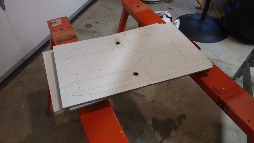
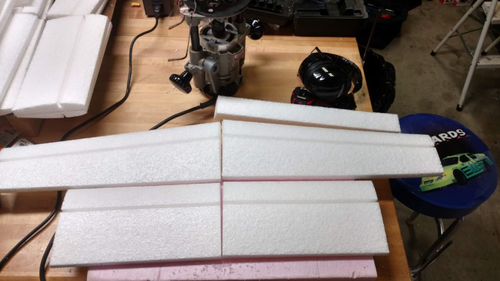
Finished building new router template boards for cleaning out the internal cavities in the fuselage and cutting the servo pocket through-holes.


Only thing missing from the foam set at this point is a canopy.
This has been an adventure of finding old tools, filling in gaps in tools by trips to Menards, and stepping back and thinking things through in terms of not using CNC to cut the parts as originally envisaged.
I already have some wood parts that were cut on the Phlatprinter for the motor mounts. When those run out, though, I’ll probably contract with a laser cutter to make more. Not sure about the stabilizer platforms. Have to look in the wood part bin out in the unfinished shop.
My manual cut parts (band saw) require layout templates. The old CalComp printer that’s followed me back and forth across Indiana and Ohio finally gave up the ghost. My one trip to FedEx/Kinkos to print on their HP was a clear indication of how inconvenient that’s going to be. So, I have a new 24″ HP printer on the way. It won’t only be used for models. I have other projects for the house and such that will make easy use of a handy large-format printer.
Next step is to finish up the canopy template and get those cut and sized. Once the new printer is here, I’ll get the taper template for the tail boom completed.
Work on the instructions needs to be done, as well. I’ll probably work on that while waiting for the printer and after finishing the canopies.
Third Post, January 5, 2019, PEC V5 progress, 01/05/2019
Received my new HP 24″ printer yesterday and spent the evening assembling and setting it up. First thing I printed was a new fuselage profile, as I had discovered that what was currently in CAD was not corresponding to the template I was using.
The old CalComp printer served me well, but it is a 20th century device. The new HP has all the current technology bells and whistles and even cuts the sheets for me. I will have to recycle the old CalComp with full honors. If anyone thinks they can fix the paper feed connection between the stepper motor and the rollers, they’re welcome to the printer for free. I will note that the only driver software I’ve been able to find is from Australia and costs $200. Maybe someone’s got more printer mojo than I do and can do it a different way. (Need to check and see if the Aussie driver will work with the new HP and if there’s a “custom paper” option in it. The HP driver doesn’t seem to like the idea of me defining my own print lengths even on a continuous roll.)
The big clue that something was wrong with my fuselage template from 2010 was the fact that the canopy printed from the current CAD didn’t fit. After dinking around a bit to verify dimensions between the real and virtual worlds, it became obvious that I had, sometime in the interim, revised the curvature of the nose.
This really isn’t too surprising. The V5 has a longer schnoz in order to balance with the lighter brushless motors. I just hadn’t remembered doing the iteration between the template that built my pilot model and now.
In any case, I was able to get the new template made and adjust the three fuselages I have already cut to match it. Fortunately, the old template was proud on one side so I could rework things to fix it.
I’m working through converting the V5 design from the original CNC router fuselage to the current manual cut fuselage. My intention originally was to have all the internal slots and everything cut on the CNC. This was driven by the Phlatprinter paradigm and using 1″ foam to feed the beast, as it were.
Now, though, I’m back to the old V3a/V4 way of doing things with the band saw and router templates. It works well enough for what it is, but putting in all the smaller, more precise slots for the carbon inserts and vertical fin is going to be more challenging.
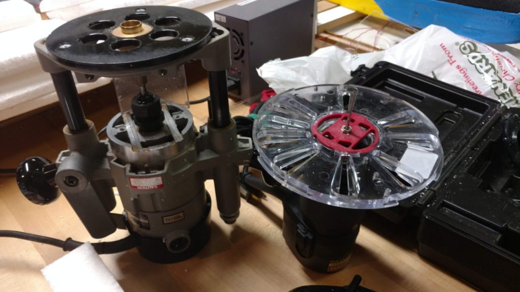
To that end, I picked up a plunge route base for my Dremel that I use for router work. The old base is not square with the world and only good for gross cuts. I think I can do the lighter internal cuts on the tail boom and front fuselage much better with a more substantial and precise base.
I really wish I could lay hands on a die cutting press to make the tail pieces. Coroplast is much happier in a die-cut environment rather than a band saw one. The edges can weld together in the stack as you cut, which is a pain, not to mention getting the double-stick tape off.
Eventually, I want to get my shop set up with a laser-cutter for doing balsa and play, a larger bed 3-axis CNC router, and a CNC foam cutter. The Phlatprinter probably still works, but I haven’t set it up yet and tested it. I think the original incarnation with the flexible polisher from Harbor Freight is probably the best way to use the thing. I tried setting it up with a Bosch router, but the weight was probably not the best for the system.
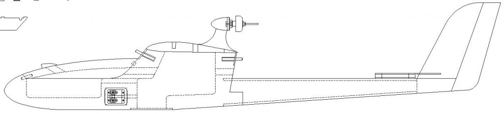
Thought I’d throw up a couple of screen shots showing the difference between the V0-V4 series and V5 fuselages. The V5 really is sleeker. I’m also going to provide direction and options for tapering both the rear of the cabin and the tail boom. The pilot proved that the Cat gets a lot slicker with just a little aerodynamic “adjustment”.

Fourth Post, January 11, 2019, Obsolescence and motor choice
So, I was poking around on “da interwebs” and confirmed what I already knew, which is that the Towerpro 2800 motors are now obsolete relics.
This led to additional poking around on various sites to see what actually is available. Turns out there are various valid options that won’t break the weight bank.
That said, I now need to design 3 different mounts for the various options, each with some level of adjustment for the variety of choices people have.
I’m still partial to Bell type motors myself, but I certainly don’t want to cut out people’s choices.
Motor pictures tomorrow.
Fifth Post, January 14, 2019, PEC V5 progress, 1/14/2019
Okay, so I promised some more pictures regarding motors.
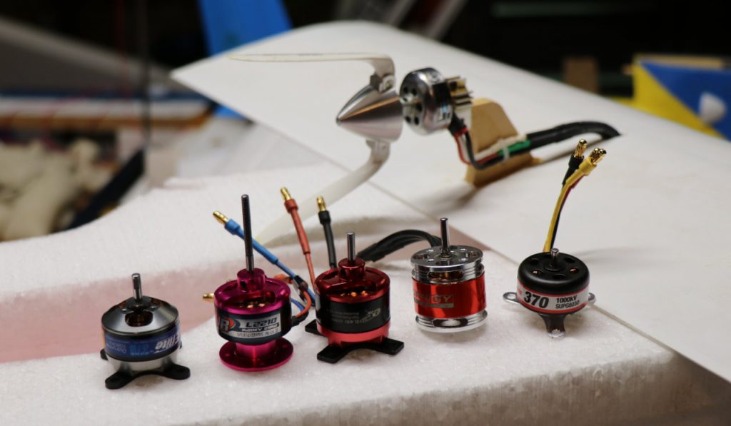
First picture is of a collection of 28 mm outrunners I had in my inventory with the trusty Towerpro 2800 hanging out in the background on V5 prototype 1. From left to right there’s an Eflite Park 370, a Turnigy Air L2210, an E-RC BL400, some Turnigy motor I thought looked cool so I bought 3 of them but I have no idea what the KvA or power limit is, and a (haha) Supertigre 370.
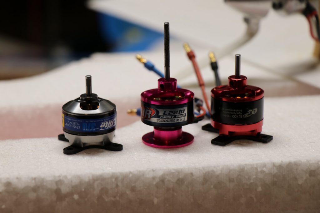
After checking around a bit, the only ones that are still available are shown in the next picture: The Eflite, the Turnigy L2210, and the E-RC BL400. So, those are going to be my basis for design for the V5 motor pylon design.
In the process of sniffing around and using my calipers, I discovered a couple of interesting things. First, the L2210 looks to be the direct descendent of the Towerpro. The assembly length is identical. The L2210 is actually 2 mm smaller in diameter than the Towerpro, but both are 1400 KvA motors.
Second, the E-RC with its cruciform mount attached is almost exactly the same installed length as the L2210. The Eflight motor is a bit shorter, but if I design for the longer, common length, then the Eflite could be fitted with spacers or a block.
The Eflite motor does have a more refined cruciform mount, though. Rounded the ends actually makes it more compact for installation. Of course, fixing that for the BL-400 just requires the judicious use of a file or a Dremel, but it’s a nice, professional touch regardless.
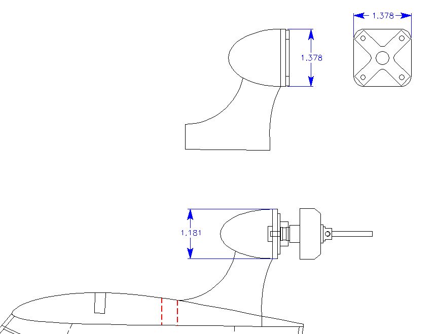
In any case, picture three is a snapshot of my design screen showing the two different mounting pylons. I messed with having one pylon for both, but it ends up making the “egg” bigger for the Turnigy install which looked weird.
The big difference between the L2210 and the Towerpro is that the Towerpro’s radial mount diameter was significantly smaller than the diameter of the motor itself. The L2210 mount is the same diameter (28 mm) as the motor. Just enough difference that I wasn’t able to use the original Towerpro mounting pylon, which sucks because I have a shelf bin full of the things after running a cut program on the old Phlatprinter many moons ago.
Next step is to do some solid modeling in 3-space and see what both the bell-type mount for the L2210 and the transitional rectangle for the other outrunners will end up looking like.
Sixth Post, February 10, 2019, Progress on Motor Mounts via Phlatprinter
So, haven’t updated for a while, but project continues.
Here’s what happened:
I designed the new motor pylons for currently available motors. I then printed out some templates, glued them to MDF board, and fired up my old reliable Delta bandsaw.
The results were…rough. Okay, just cutting the templates reminded me why using a bandsaw on foam is okay but wood parts really aren’t amenable to that process, at least not enough for me since my eyes are going and I have way too much caffeine in my system.
I put things aside for a night to think about it. Somehow between that bandsaw session and waking up the next morning, I had decided: I would get my old Phlatprinter running again and let the machine do it.
For cognitive reference, had I stopped to notice, this is right up there with, “I shall summon a small CNC demon to do my handiwork as soon as I find a gypsy with a goat.”
In any case, I have reaffirmed that my impression that CNC is very much its own hobby that swallows time at a geometric rate depending on how much you want out of it. I knew it before. I have re-learned it again.
I am now much more appreciative of what Mark and Trish accomplished with the Phlatprinter machines. Now that I’ve been around the block a bit more, I recognize how great their accuracy actually is for what level of investment was involved.
That said, I still had to contact CNC-USB and figure out why I was having trouble talking to the machine. Once they got me straightened out, and once I re-learned how to calibrate the thing, and once I figured out the archane art of using SketchuCAM to made GCODE files, it’s actually working right and reliably. Which makes me wonder why younger Darwin had so much trouble coming out of his navel-gazing and realizing what he could do with the tool.
Thus, I have now finished Phlatprinter-friendly versions of both the Radial and Bulkhead style motor mounts.
Here’s a link to a video of the Phlatprinter doing its thing on the pylons:
Seventh Post, February 12, 2019, Closing in on finishing the radial mount
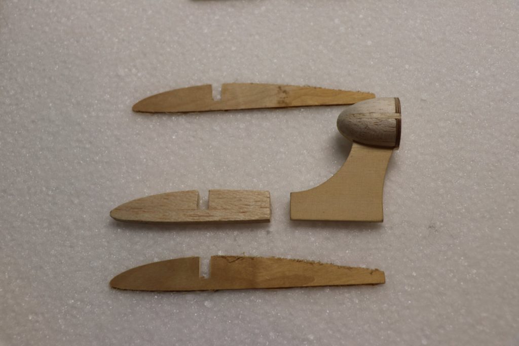
Stayed up late last night after running the balsa side-bolsters on the Phlatprinter and finished up the radial mount “egg”.
Did some digging in my “box of stock” that I’d cut previously and found enough bits to finish at least one new motor mount.
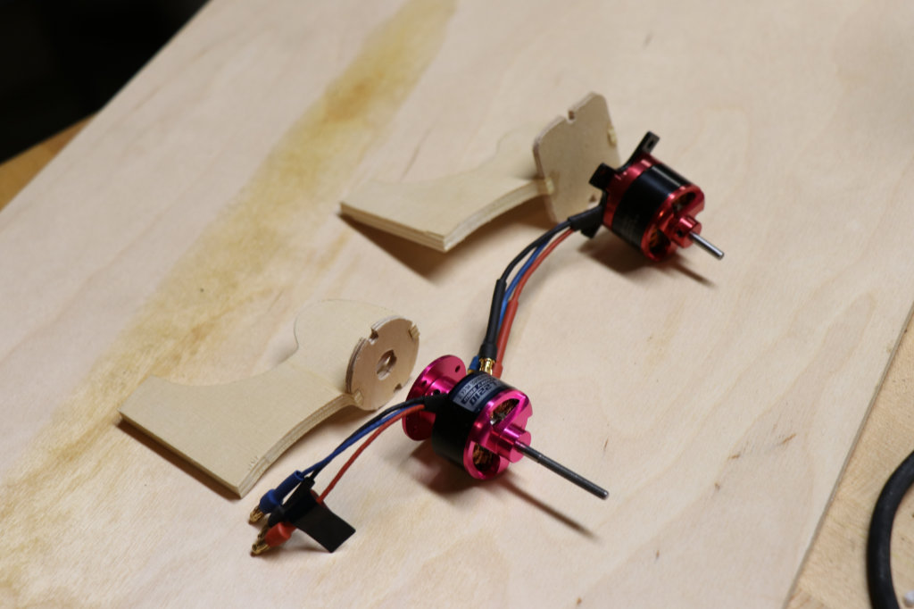
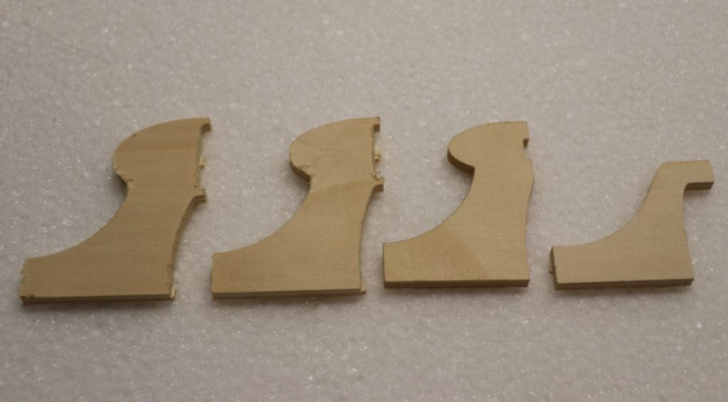
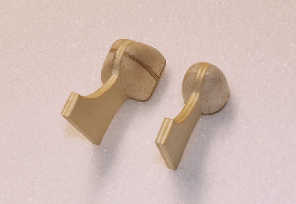
Pictures below show a) the new radial mount along with the bits to finish the center section “root rib” and b) a comparison of mounts, newest on the left, oldest on the right. Center line of the new mounts have been adjusted to provide 0.5 inch clearance to the tail boom for 8 inch props. Old mounts were a wee bit closer to the boom than I really liked.
Should probably have the radial mount root rib assembly done tomorrow. Still looking for the original CNC cut files for the extra parts. May have to re-create them.
Eighth Post, February 18, 2019
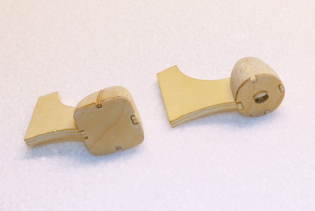
Finished up the new side bolsters for the cruciform mount and assembled that section. Whittling the balsa fill to shape and sanding it into submission is definitely more challenging than for the radial mount.
Point of reference, the side bolsters on the cruciform are 3.0 mm plywood. (3.0 is not 1/8″, Midwest. Quit lying on your labels. Screws with my tolerance stack up.) I used ply because I really had to be careful with the balsa side bolsters on the radial mount to make sure I only cut and sanded up to the edge to maintain the curvature.
That said, next time I’m using lite-ply. It’s still tougher than balsa and I have better things to use plywood for (like the press plates).
The cruciform mount is noticeably heavier than the radial, which should have been obvious before I made it, but I got in a hurry. In the instructions, I’m going to suggest cutting away some of the inner corners of the fill blocks to lighten them while still providing enough wood for shaping.
Can be done for the radial, too, but the cruciform will need that whereas it’s just “nice” for the radial.
I’ve pretty much decided that the bog-stock V5 will be based off the bell motor. Having a cruciform option is okay, but it’s something that a customer will have to want to have for whatever reason. The plane will be better for its intended use with the bell motor.
That vaguely segues into a discussion of design intent and avoiding line to line designing that I’ve been thinking about.
The Push-E Cat has a purpose to its design, which is to be a rugged and forgiving trainer and all round fun plane. It’s not a pylon racer or an ALES competition model. It goes up, flies for a long time, and bounces when it smacks terra firma inadvertently. The fact that it actually does glide really well is a bonus. What matters most are gentle flight characteristics, ease of assembly, ease of maintenance, and overall cast-iron durability.
The Ease of Assembly bit is one that takes more work. EPP models can very quickly become challenging because the base material is not particularly fond of being glued with epoxy or CyA. Oh, it will work. But when you smack into the very large immovable round object we all stand on, regular modeling glues don’t have sufficient “give” and you end up ripping pieces out of the parent foam rather dramatically.
This ends up translating into added complexity as you specify the appropriate adhesive for each sub-task on an airplane. The PEC, for example, still can use standard glues for assembling the motor mount and dowel carriers. However, to glue hard wooden bits to the foam itself, you need to use polyurethanes like Gorilla Glue and Pro-Bond. For carbon fiber stays, the best option is E6800 or some other Goop derivative. Plus the foam has to be prepped for covering because regular tapes or iron-ons just can’t stick to bare EPP. At that point, it becomes something of a free-for-all with everything from Elmer’s Glue thinned with water to 3M77 or 3M90 and even DAP Weldwood, both the stinky and the water-based kind. I honestly don’t know which is best and I’ve tried them all.
Frustrating. And then you have to try and put that into instructions that someone who’s never built a model can understand and has no idea why they need 3 or 4 adhesives instead of just one.
Ah, for the days of Ambroid. Blarg.
The reason I’ve wandered into that is that if you’re going to try and take complexity out of something for the end user, you have to drive necessary complexity out of sight and into the base design. Things like making sure your notches and spacing are set up to deal with the fact that 3.0 mm is not 1/8″ or the fact that real materials vary and if you try to design something without any tolerance between the parts (i.e. “line to line”) then things won’t fit right out of the box without some rather particular modifications by the end user with a hobby knife and sanding block.
Which makes a model harder to build. Which can discourage someone who is just starting. Which causes the primary function of the product to remain unachieved.
So, the PEC V5 has two areas that I am significantly concerned about in terms of ease of assembly: 1) The motor mount and 2) The wing joiners.
The motor mount I believe I have muscled through and can finish up the design work on enough to generate the production CNC programs. That’s why I lingered on it so long.
The wing joiners, well, I haven’t really gotten that sorted yet.
I’d love to have removable wing tip for two important reasons: 1) transport-ability and 2) ease of maintenance/replacement.
The issue is that adding removable tips to a design can be a major complication to building. It’s far easier to drop in a ply joiner and call it good than it is to engineer and build a properly aligned and durable joiner system.
I think I have an idea of how to do it, but it will require some investment on my part not just of design but of tooling and sourcing to make it happen. This is an example of driving the complexity away from the end user and into the baliwick of the design itself.
Choices like that are part of any engineering design:
“Should we do this?”
“Does it add too much cost?”
“Will the customer be able to complete that task?”
“Do we need to control the tolerances so that the product will function correctly?”
“Is letting the customer do it too much risk?”
The answers to those questions go back to the intended purpose of the design and the expected capabilities of the target customer base. And every design feature has to be looked at going back to the original purpose of the project.
Anyway, just the muttered musings of an aging career design engineer as plods his way to actually making a model reasonable for others to build and enjoy.
Ninth Post, March 12, 2019, Cruciform versus Radial Mount and Design Considerations
Checking in to let everyone know that the project continues.
I have been elsewise occupied with helping deal with the fallout from the passing of Ray Hays of Skybench Aerotech fame. There are lessons to be learned from this, in addition to simply doing what one can to help a family deal with a mountain of model business/personal modeling possessions.
Since I’ve been reworking the V5 design documentation and rationalizing the design, I have been attempting to bring my experience as a design team lead for a major manufacturer into what I’m doing in terms of documentation. Not that I need the whole corporate kit and caboodle, but there are benefits to having a robust engineering documentation structure to work with.
Ray’s passing drove that lesson home. Frankly, if it wasn’t for the support of the people with engineering backgrounds who did his laser cutting, the kit documentation would be functionally illegible, and that has a direct impact on the value his family can obtain from the sale of the business and kit rights associated with it.
Some folks do get it. Established kit manufacturers definitely get it. But often, less focused more artsy or sales type people don’t really get it. If you don’t properly document a design, it really doesn’t exist, and putting together a product without decent documentation is a nightmare and customer service whirlpool of effort.
Based on that, I’ve been spending some time getting drawing formats sorted out for my CAD system and generating a “design documentation database” which is just a file structure at this point for saving the various required information for each PART of a design as well as the overall assembly models.
For example:
A solid model of the part.
A drawing of the part with enough dimensions on it to be used to check a physical part to make sure it meets design requirements.
The CAD file used to drive the software that generates either CNC router or Laser Cutter tool paths.
The actual toolpaths for the parts (if applicable)
For a design you have to provide:
A Bill of Material (BOM) that will drive your packaging requirements (and quality control) as well as be included with the instructions so that the customer can verify the contents of a package.
Instructions
Plans with important dimensional directions and assembly notes
Assembly illustration source files (illustrations can be used either in instructions or on plans)
My own part numbering system goes a bit beyond that, as part drawings call out raw material parts that are used to make the part in question (as in, motor mount pylons will refer to a pattern drawing for production, which then refers to the bulk raw material to be used). This is part of how you plan for what raw material you need to have on hand for a run of “X” kits.
The effect of all these considerations is that I have slowed down a bit to make sure I set this up correctly. That way, if I croak, my family won’t be completely in the dark about what all those numbered bins of stuff are for and what value each has inherent in it.
Of course, since I’m not doing the full-on business thing, what it really does is let me keep things organized so I can stay out of my own way and out of trouble.
Tenth Post, May 21, 2019
Checking in to let everyone know that the project continues.
I have been elsewise occupied with helping deal with the fallout from the passing of Ray Hays of Skybench Aerotech fame. There are lessons to be learned from this, in addition to simply doing what one can to help a family deal with a mountain of model business/personal modeling possessions.
Since I’ve been reworking the V5 design documentation and rationalizing the design, I have been attempting to bring my experience as a design team lead for a major manufacturer into what I’m doing in terms of documentation. Not that I need the whole corporate kit and caboodle, but there are benefits to having a robust engineering documentation structure to work with.
Ray’s passing drove that lesson home. Frankly, if it wasn’t for the support of the people with engineering backgrounds who did his laser cutting, the kit documentation would be functionally illegible, and that has a direct impact on the value his family can obtain from the sale of the business and kit rights associated with it.
Some folks do get it. Established kit manufacturers definitely get it. But often, less focused more artsy or sales type people don’t really get it. If you don’t properly document a design, it really doesn’t exist, and putting together a product without decent documentation is a nightmare and customer service whirlpool of effort.
Based on that, I’ve been spending some time getting drawing formats sorted out for my CAD system and generating a “design documentation database” which is just a file structure at this point for saving the various required information for each PART of a design as well as the overall assembly models.
For example:
A solid model of the part.
A drawing of the part with enough dimensions on it to be used to check a physical part to make sure it meets design requirements.
The CAD file used to drive the software that generates either CNC router or Laser Cutter tool paths.
The actual toolpaths for the parts (if applicable)
For a design you have to provide:
A Bill of Material (BOM) that will drive your packaging requirements (and quality control) as well as be included with the instructions so that the customer can verify the contents of a package.
Instructiions
Plans with important dimensional directions and assembly notes
Assembly illustration source files (illustrations can be used either in instructions or on plans)
My own part numbering system goes a bit beyond that, as part drawings call out raw material parts that are used to make the part in question (as in, motor mount pylons will refer to a pattern drawing for production, which then refers to the bulk raw material to be used). This is part of how you plan for what raw material you need to have on hand for a run of “X” kits.
The effect of all these considerations is that I have slowed down a bit to make sure I set this up correctly. That way, if I croak, my family won’t be completely in the dark about what all those numbered bins of stuff are for and what value each has inherent in it.
Of course, since I’m not doing the full-on business thing, what it really does is let me keep things organized so I can stay out of my own way and out of trouble.
Eleventh Post, May 21, 2019
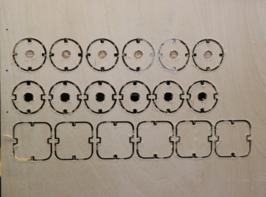
Have burned parts for PEC V5 with new laser cutter.
In other news, found source of shop stench in trap pan of garage refrigerator. Very gross and completely unidentified organic goo.