What I’ve been up to since the last post…

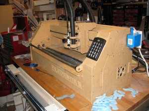
End shot of the new Phlatprinter from Phlatboyz

Time Sink par excellance: The Phlatprinter ///

So, as you can see from the picture above, my Phlatprinter /// arrived from Phlatboyz right before Christmas, 2010.  This fact alone pretty much explains the delay in my updates to the blog and the lack of progress with the Push-E Cat V5 at this juncture.  Considering that the Phlatprinter is something of a linchpin to my plans for resurrecting Garrison Aerodrome, I hope that I’ll be excused for the distraction.

First off, I have to give props to Mark and Trish Carew of Phlatboyz.  As fledgling entrepreneurs, they rock.  Their team commitment to customer service and community building efforts are top notch.  They are doing their best to build a quality organization from the ground up and it shows.  When you add in their innovative product lines and well-thought-out designs, you can tell they are on the path to success.

Building the Phlatprinter /// was really easy.  In fact, it makes me ashamed that building a Push-E Cat can’t be as easy.  Then again, you don’t slam a Phlatprinter into the ground at 30 knots and expect to pick it up, brush it off, and then launch it again, so…but it was actually a lot of fun to put the unit together.

After it was together, though, was when the real learning curve kicked off.  First off, I had to accept the fact that the only way I was going to get parts out of it was to learn ANOTHER CAD program, which happens to be free but…anyway, that’s Google SketchUp.  Then I had to learn the hard way that the bastards at Google killed the DXF import feature of version 7.somethingorother of the free software.  This meant tracking down version 7.0 to use.  After that, there’s the script programs that have to be rounded up and installed into SketchUp in order to generate the G-code output that a THIRD program, CNCUSB, uses to actually drive the bloody machine.

I spent a lot of late nights banging my head on my desk (figuratively) following this path down to where I could actually export files (STL and DXF) out of my full-on CAD package into SketchUp and then out again to CNCUSB, but I did it.

Sadly, that’s when another set of issues cropped up.  See, the thing is that the Phlatprinter /// is actually a very new product.  This means there’s some teething issues, primarily in the main drive rollers.  There’s been a Phlat-community wide effort to resolve this issue and it does look like things are finally coming to a conclusion.  Unfortunately, it’s slowed down my learning curve and my drive forward to have the machine cutting my parts by now.  Heck, when you can’t trust the machine, you can’t really get a good feel for bits and feed rates and all the other minutia that CNC part cutting entails.  This means my frustration level has been getting the better of my usually calm demeanor.

Yeah, my kids and wife would say I’ve been something of a true bastard of a shop hermit lately.  This happens when your shiny new CNC machine keeps effing up stock with missed steps and whatnot.

I swear a lot when that happens.  There will be no apologies forthcoming for such behavior, either.

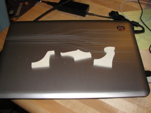
Three CNC cut motor mounts

Three successfully cut CNC motor mount centers

So, I’ve been spending a lot of time trying to make the PP3 make at least a few decent parts until such time as a decent permanent fix is codified and blessed by Mark and Trish.  Lately, that means by the time I wander back in and even begin to think of making a blog post, I’m too bushed to mess with it.

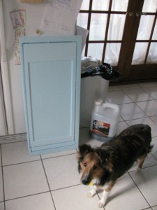
In any case, I do have a couple of successes so far.  I managed to cut a tool for holding 1/4″ lite-ply as it goes through the Phlatprinter.  I also managed to get a nice stack of acceptable motor mount middles out of the machine between fiddling with the main rollers in a vain attempt to deal with the missed X-axis steps.

First tool alongside Indy the Shop Puppy

First tool cut alongside Indy the Shop Puppy

Still, for all my bitchin’, I’ve learned a lot.  I now know how to work the CAD to SketchUp to CNCUSB interface.  I understand more about how the various pieces of the Phlatprinter have to work together in order to assure a good cut.  The new HP laptop on my bench is a visual reminder of the lesson that you can’t use a netbook to cut 3D surfaces with CNCUSB.  Also, you must always remember to remove the power supply from the printer cabinet before you tilt the printer up to tighten the x-axis drive rollers.  I’m not sure how much more abuse the Z-axis mosfet on the driver board can take.

And thus I wind down to the end for tonight, waiting with bated breath for the “final solution” to the roller problem to be announced while plotting madly to cut everything except wing cores on this new tool.  That’s probably too ambitious and the PP3 really is more of a hobbyist’s tool than a production tool, but I’m still convinced that this one device (and any other family members I buy from Phlatboyz in the near future) will be stepping stones to whatever success I managed to eke out of this effort.

Posted in CNC, Kit Projects, News, Tooling | Leave a comment

Note to self:

CAD shot illustration of fuselage components for the V5 instructions.

Well, at least I made a bit of progress with my CAD work.

Install trailing edge CF reinforcements prior to laying on kraft paper composite – and skip the whole “clear Minwax polyurethane” thing.

Yes, Virginia, I managed to re-create the whole V2 “scimitar wing” fiasco.  Shrinkage is a b***h.

Posted in Push-E Cat V5 | Leave a comment

Placing domestic water fowl in linear formations

Shot of a semi-complete wing tip for the aileron Push-E Cat proto

Behold my CF racing stripes...

It’s driving me buggy, but I’m getting it done.  Slowly but surely I’m amassing the information I need to be able to lead a customer through the process of building an aileron Push-E Cat.

If it was just me slapping some one-off together for a weekend fly-in, that’s one thing.  When you’re putting something together that you want to impress people enough that they want to have one of their own, well, you tend to try and do better – at least I do.

And I suppose that’s a goal I should express.  I know that anything I put together in my ad hoc shop isn’t going to look like the mass-produced stuff coming out of Tower Hobbies or Sky King or whatever.  Heck, I don’t do ARFs to begin with.  Still, when a customer gets one of my kits and opens it up, I want to do my best to make sure that they’re happy with the amount of effort I put into making it the best I could.

In short, I want to maintain the engineering rep I built up with my earlier work.

Shot of the bottom of the aileron PEC proto wing set as of 12/17/2010

Where I left off today, all servo wire cavities capped

That’s the long and short of why I’m working my way through this aileron wing while bouncing back and forth between the shop and my CAD tube.  I could just sit here and wave my hands and pretend to know what I’m talking about when I tell people how to install their servos, cut live hinges, install the kraft paper, and route the wire channels – but I won’t.

But, you know, having said that, I think I need to mention that people who are willing to offer suggestions and feedback are the core of making a product better.  Not that every suggestion is something that can be integrated into a production kit – some goals or ideas are just too specific or eclectic or some techniques not exactly right for a particular airframe.  Still, lots of ideas and thoughts have driven the Push-E Cat to evolve and similar things will push other project forward.

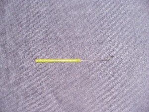
.047 push rod test sample

Change! .047 Push rod wire mean no servo arm drilling

For example, I saw a blog post about E-200 pylon racing in Utah on RC Groups the other day.  I immediately pulled up the wing planform for the Manx and Hot Cat and realized that all I had to do was add an inch to either wing panel and the designs would be legal.  On top of that, by looking at the current planes on their web page, I realized that I had been over-thinking the motor installation revisions necessary to put brushless motors in the EPP airframes.

Another example are the hints, suggestions, and examples of modifications that people offer up on the Push-E Cat thread on RC Groups.  I can’t express how great it is that there are folks (Hi, Bill!) willing to share their ideas and insights.  I’m of the opinion that listening is one of the most important skills an engineer has.  Another one is the ability to realize that their idea may not be the best one and be willing to change gears.

An example of this is the 2 mm coroplast tail on the V5.  I’d given up on coroplast. I had convinced myself that the material had its uses but not in the ass-end of my aircraft.  Yet, the people in the thread pointed out to me how 2 mm with carbon fiber reinforcement was still viable.  I decided to try it and I’m glad I did because the new tail works great.

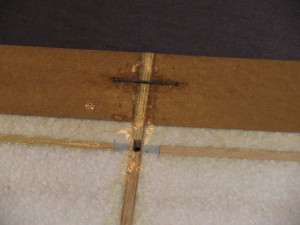
Rear cf joiner and center servo pass-through holes

Carbon pops up everywhere on the V5

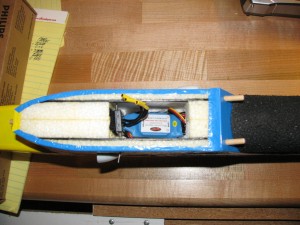
The Push-E Cat contains a lot of change.  Denny innovated the laminated motor mount.  I grabbed that idea and expanded on it for the V5.  The dowel carrier assemblies came out of customer feedback about dowels ripping out of the EPP.  The servo-block style mounting came from people complaining bout installing the servos buried in the middle of the fuselage.  The V5 mounts its speed control in the main cabin and I’ve added flow-through cooling channels to facilitate that.  Why?  Because people don’t want to put their speed control on top of the wing.  It used to make sense when we were using Jeti 10 compact speed controls and 6V Speed 400 motors.  Now?  Listen to the customer.

Other changes, like how I’m using the kraft paper and 3M 90 for the trailing edge are more production and engineering related.  I’m fairly sure it’s going to work out great.  Am I 100% sure? Oh, hell no.  That’s why I’m slapping together an aileron wing while simultaneously trying to write the instructions for the kit.  It’s probably going to cost me any Christmas shipping at this point but that’s just the way it is.  If it doesn’t work, I’m back to balsa for the trailing edge and the instructions are completely different.  I’ve got to know now.

Close up shot of carbon fiber aileron reinforcement

Live hinges for the win!

Then again, I may not be 100% sure, but I’m still pretty doggone sure.  The addition of the 1/16″ rod to the aileron and the sub-trailing edge really add a lot and the wing hasn’t even been covered yet.  Once you iron on the Ultracote, I think the structure is going to be awesome.  On top of that, the live hinge is sweet.  Just say no to tape hinges.  I kind of like that.

Speaking of Ultracote, I suspect given the information from the Rite-wing thread, that if you use 3M 90 as the foam-prep before taping or covering, it probably doesn’t matter what covering you use (so long as it’s decent quality.)  I’ll continue to use Ultracote because I’m used to it.  However, the broader color range and easier availability of Monokote kind of makes me want to do some tests.  Monokote is pretty strong linearly, unlike some other more “gooey” coverings.  It’s more brittle than Ultracote, though, and goes on at a higher temperature IIRC.  That might make it hard on thin trailing edges like the V5 features.

Of course, that’s why we test.

That’s pretty much it for tonight.  I’d post more of the instruction pages, but they’re all text at this point.  I’m up to doing the bill of material complete with graphics and the graphics bit requires me to do some actual solid modeling.  Ergo, I’m banging my head against the CAD tube again.  Should have some nice pages to share here tomorrow.

Posted in News, Push-E Cat V5 | Leave a comment

End Stretch

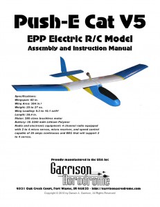
Cover for the Push-E Cat V5 instructions

Page one...FINISHED!

Tick tock goes the clock and I’m running down the minutes until I actually begin shipping Push-E Cats again.  First clue that things are getting close is the cover page in the image shown at right, here.  Yes, Virginia, I am actually doing real live page layout in a desktop publisher.  Fear the coming word dumpage.

I would like to note at this time that it took many more hours to actually futz around with the stupid picture of the Push-E Cat prototype for the cover than it did to do actual honest to goodness solid CAD exploded views of the motor mounts.  I HATE image editing.  Fortunately, it’s not an unreasoning hatred.  I know that I hate it because I don’t know what I’m doing.  All day today as I was messing with the picture, I kept thinking to myself, “Self, go to IPFW in the Spring and take a damned photo editing class.  You’re gonna need it.”

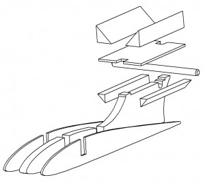
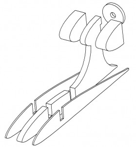
Exploded view of the V-block mount.

The PEC V5 will accept inrunners.

Of course, today did not lack for issues with CAD, either.  I had not touched my copy of Vellum Solids seriously since I last did an update to the V3a instructions in 2002.  As a result, when I started in on doing the illustrations based off my Vellum layouts, it was like learning to ride a unicycle all over again. The extra special bonus is that Solids seems to hate the computer I’m currently using.  It runs fine on my old computer (which currently is in the service of my eldest daughter), but it really dislikes being forced to run on my “downgraded” XP box (i.e. I killed the Vista install that came on my box and replaced it with XP because, honestly, Vista sucked.)

In any case, it took a morning epiphany that “Maybe the software is screwed up” before I finally managed to break through and start making progress again.

Bulkhead mount for outrunners, exploded

But I think outrunners are probably better in most cases

So, having face a variety of issues that have little or nothing to do with actually cutting parts for kits, I will sit down tomorrow to do battle with the dreaded CAD and publishing systems to try and knock out the instructions for this thing.

One thing about making kits, there’s always one more thing.  Still, I’ve done this before so I do have some idea of what I’m up against.  And going through this for the PEC V5 should make doing the same thing for the Flat Cat a cinch.

Right now, my biggest ancillary worry is finalizing the procedure for installing the ailerons.  After that, I’m running a test to compare using .047 wire for all push rods on the servo ends as opposed to using .063 wire.  With all these teeny servos, when you push through a 1/16″ hole in the arm for the rod, there’s damned little nylon left to absorb the shock.  If you use .047, the Z-bend slips right into the little factory holes.

I think it’s going to work.  I’m just waiting for the Pro-Bond to set before I try a “pull-out” test.

After that, all that’s left is a quick design for some plywood control horns for the PEC V5 ailerons and the Flat Cat everything.  I can almost taste the EPP smoke and feel the router vibrations as I type.

Posted in Push-E Cat V5 | Leave a comment

Behold the old-schooly goodness…

Old school Push-E Cat

Old school Push-E Cat

Hey, Folks:

As an FYI, I’ve uploaded the old, old Garrison Aerodrome web site to the new Garrison Aerodrome server.  I chose to do this for a couple of reasons: 1) Because some site-squatting jerkwads snagged rc-aero.com a while back and even usurped the old web site naming structure in order to hog off all the links that used to point back to my old pages and 2) Because I wanted to make all the old pictures and stuff available for folks to gawk at so that you can see how far things have come in 12 short years.

Disclaimer: All contact information, pricing information, and availability information on these pages is obsolete and completely unreliable.  Things may or may not work depending on how HTML and Java have changed over the years.  Also, any links whether shown on the links page or not are questionable at best if not absolutely useless out of hand.  If you want to get hold of me or buy my stuff, be sure to start at https://garrisonaerodrome.com

Anyway, the link to the old pages is here.  Enjoy your trip down memory lane.

Posted in News | Leave a comment

The “Lite” lamination process

So, yesterday I got it into my head to take pictures of how I’ve been applying the kraft paper laminate to the trailing edge of my latest prototype Push-E Cat wing build.  Then, having obtained the pictures, I got distracted and wandered off to work on things like solid models and instructions.  Then today my goodie package from Hobby King finally arrived and…

Anyway, here’s the pictorial walk though of the process.  Oh, and one thing right up front: glue in the spar first when you’re doing the wing tips.  This is exactly backwards from the way you do the mains, but the mains don’t have washout.

The one thing I always remind folks who are building Push-E Cats is that you’re not building a “foamie”.  Some people get it in their heads that anything that uses foam as a base material is some sort of cheap-ass disposable thing for filling in a gap in the flying season.  What you’re building is a composite airframe that designed for maximum durability without compromising flight characteristics.  “Composite” means “made of multiple materials” not “made exclusively of expensive carbon fiber and epoxy”.  The use of the kraft paper is a prime example of this.  You choose materials for composite construction that complement and support each other by adding necessary characteristics to achieve performance goals.

Just sayin’.  Moving on…

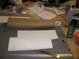
All the stuff you'll be needed, sans newspaper

First, you gather up all the stuff you need.

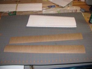
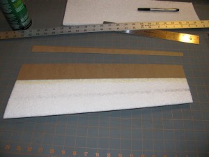
To do this, you need the kraft paper, some straight edges, a ruler, a pen, an X-acto or other really sharp piece of knife, the 3m 90 spray adhesive, and a goodly amount of newspaper or other sacrificial spread-it-around to keep the glue off of your stuff.

Cutting kraft paper strips to width

Then you slice yourself some paper with the sharpness

Step one is to cut some 3″ wide strips of KP laminate that are wider than the core section is long.  Use a straight edge to make sure you have a straight line to work with when you go to stick the paper to the core.

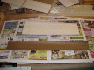
Step two (which you can also see in the picture above), is to mark your core as to where you want to line up the paper.  For the PEC V5 wing tips, you measure 4.5 inches from the leading edge at the root and 3.5 inches at the tip.  Don’t measure from the trailing edge because that varies wildly depending on hot wire path variation. (Yeah, I know, gravity drag stuff adds in a bit of variability, but it doesn’t affect the flight characteristics at all at this level.  Get over it until I sell enough kits to afford a hot-wire CNC.)

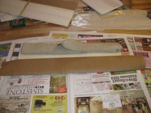
Applying glue to the KP lam and wing core

Den youse spray da bejeezus outta da parts with the glue, see?

Step three, lay down the newspaper and apply the adhesive.  Okay, a word or two about 3M 90, why I’m using this, and how it’s different from our old standby, 3M 77.

3M 90 is a serious spray adhesive intended for installing things like kickplates, heavy laminate tops, and other things that don’t have a problem being coated with solvents like lacquer thinner, toulene, acetone, etc (which is EPP in a nutshell.  It simply doesn’t care when you spray stuff like this on.)  The primary advantage for me and the Push-E Cat is that it is FAR more thermally stable than 3M 77 ever was.  3M 77 was intended, as near as I can figure it, to glue things like paper and styrofoam together.  Then 3M went suddenly stupid and added acetone to the mix, which nixed using 77 for styrofoam.  (They have since added an entirely separate spray adhesive for styrofoam.  I saw it on the shelf at Menards.)  The problem with 3M 77 has always been that on a hot summer day, it simply gives up.  3M 90 does not.

The downside of this is that you absolutely must not use 3M 90 in an enclosed space with inadequate ventilation or, in my case, overuse it in a space with inadequate ventilation.  For modelers, it’s probably not much of an issue.  If you were using it in a production environment, well…anyhow, don’t be stupid and gas yourself or — worse — allow the fumes to build up to the point where the pilot light on your water heater generates a fireball in your house or shop.

Which could happen if you’re really, really careless or just too damned stupid to live.

So, just to make sure that we’re all on the same page: 3M 77 – not particularly dangerous but not particularly suitable for anything that’ll ever get warm or see sunshine (I use it all the time in the shop to make templates, for example.)  3M 90 – will hold your plane together all summer long but you better treat it with some respect or it’ll bite you (i.e. if you’re feeling woozy, for Christ’s sake open a window and get out of the damned room before you croak — or explode.)

And just to tamp down any pending panic attacks: I did all of this in my garage shop with a kerosene heater burning on the far side and right in front of my gas-fired water heater and furnace.  The key is to do a little and then let the air clear between steps so that you’re not building up a dangerous level of solvent fumes at any time.

Anyway, on the practical side, 3M 90 goes down a little differently than 3M 77, so you need to be prepared for it.  77 comes out as a go-everywhere mist, which is annoying as hell sometimes – floats all over the shop and coats everything within a 5 foot radius with a dust-catching adhesive tack.  90, on the other hand, is much better to work with.  The material is more dense and the nozzle dispenses it as a “lace” type spray.  It goes where you spray it and pretty much nowhere else.  The down side of this is that you need to make a minimum of three passes over the target surfaces to make sure you’ve laid down a proper coating.  The best part of 90 is that once the volatiles gas off, the adhesive won’t garner dust bunnies.  It’ll still serve as a good surface for ironing on the Ultracote later but, unlike 77, it’s not perpetually tacky.

When you’re ready to apply the adhesive, do it like you’re spray painting, where you start spraying off of to the side of your parts and then stroke along the length.  Go over it a minimum of 3 times without letting the glue “pool” (which extends the time to “tack” interminably.)  You get a 10 minute working window from the time you spray to the time that the adhesive quits wanting to bond properly.  Usually, within 3 minutes you’re ready to rock as noted by tapping your knuckle against the adhesive surface and feeling tack without picking up any adhesive on your skin.

Lining up your homemade kraft paper tape on the wing core

Flip the paper over and line it up on the core

Okay, a couple of things on step four that are kind of inobvious from the picture: first off, the tip core has been securely weighted down in the core bed using some of my favorite tool in the world, shot bags.  The reason for this is the aforementioned washout which is designed and cut into the wing tip cores.  Given how flexible EPP is, it would be really easy to roll the washout away on a flat surface or otherwise twist the core if you didn’t take some precautions, especially since the kraft paper laminate will essentially “lock down” the twist in the wing at this point.

Point two, you want to make sure that you rub the paper down into the core firmly on every square inch of the mating surface.  Use a small paint roller if you don’t trust your fingertips.  Make sure that you get the glue to mate everywhere you possible can.  I work from the middle out to the ends after carefully lining up the edge of the laminate with the line I marked on the core first.  It’s worked really well so far with no bubbles, creases, or ripples.

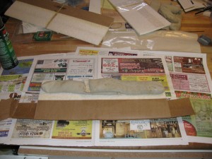
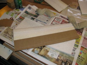
Applying kraft paper laminate to the bottom of the trailing edge.

Leveraging the core beds as best we can to preserve washout.

So, what I do after I get the top surface laminate rubbed down is use the X-acto knife to trim the excess from either end of the core.  I do NOT trim the trailing edge, just the core ends so that I can see what I’m doing and keep the next sheet of kp lam from sticking the first one except at the trailing edge.

Right, so what you do then is flip the core over, measure your alignment lines on the bottom if you haven’t already done it, and then get the next piece of kp lam that you cut. earlier.  Spread out some fresh newsprint and repeat the 3M 90 spray fest.

Then you line up the straight edge of the kp lam with the line on the core like before.  However, other than tapping the very edge to hold it in place, don’t rub it down.  Instead, flip the core over and put it back in the core bed.  Then press the whole mess down on the core bed, rubbing back and forth on top of the first KP lam layer you put down.  One quick point here, though: do NOT press the trailing edge together.  Keep your attention focused on the foam-paper interface, not the paper-paper interface.

The goal of this exercise is to lock in the washout angle as best you can.  It’s important here because once your get the second piece of kp lam put on, that trailing edge isn’t going anywhere without a lot of encouragement.

Crimping the trailing edge laminates to make a clean, straight line.

Crimp the TE on a flat surface for a straight TE

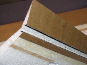
After you’ve made sure the kp lam is firmly adhered to the foam, you can then put the core on a flat surface and run your thumb along the trailing edge to “crimp” the paper together for a razor sharp line.

Trim excess kp lam for finished trailing edge

Cut off everything that doesn't look like a wing.

And, at long last, we’re ready to make that final trip.  Measure back 7 inches at the root and 5 inches at the tip, line up the straight edge, and then slice off the excess from the trailing edge with your X-acto.

All done!  Tomorrow I should have some pictures and discussion about the motors and stuff I just received and I’ll be looking for recommendations, too.

Posted in Push-E Cat V5 | Leave a comment

The first official “Lite” trailing edge

Shot of a prototype Push-E Cat V5 wing with kraft paper trailing edge applied

Oooh. Straight and smooth and NO SANDING!

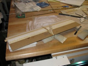
As promised, tonight I’m sharing a picture of the latest prototype wing I’m working on.  This shot shows the final result of applying the kraft paper reinforcement to the trailing edge of a Push-E Cat V5 center section.

As you can see, the result is pretty darned nice looking.  The best part is that I didn’t have to glue trailing edge stock to the EPP and then sand the ever loving bejeezus out of it.  Instead, all I had to do was mark some guide lines on the EPP, cut my kraft paper out with a straight edge, apply 3M 90 to both the EPP and one side of the paper, and then apply the paper like tape to the foam.  The only thing to do after that is hit the paper with a coat of clear polyurethane sealer (aka Varathane or Minwax) to keep the paper sealed against moisture intrusion.

It’s about that easy.

The best thing about this, other than the easy of doing it, is that you can basically cut out control surfaces.  The resulting reinforcement really stiffens the trailing edge, so if you’re going polyhedral, you’re basically done.  For ailerons and flaps, though, all it takes is a little careful knife work and some selective carbon fiber stiffening and your control surfaces are done.

My plan for this particular wing is to go ahead and finish it with ailerons.  I’ll be posting update pictures as I go along.

Posted in Prototypes, Push-E Cat V5 | Leave a comment

V5 Push-E Cat News Update for December 5, 2010

Yeah, I’d put something catchier for the post title if I could actually come up with something pithy to say.  However, that would be oddly disrespectful to the amount of slog it has taken to get this model put together.

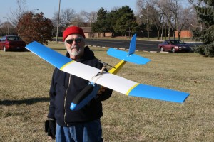
Dave Held poses with the V5 Prototype

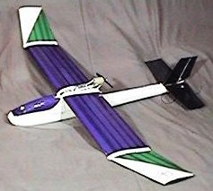
Push-E Cat V5 prototype

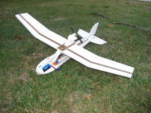
Anyway, have a picture!  This is the V5 “semi-light” prototype.  It weighs 24.7 ounces using a Towerpro motor with a Master Airscrew 7×5 prop and a 2200 mAh Thunder Power 3S lipo pack.  The servos are HS-65’s from Hitec.  The receiver is a 7000 series from Spectrum on 2.4.  The speed control is the old, nasty Polk 18 amp that Denny used to provide out of Polecat.

Shot of the PEC V5 Prototype in frame with some jet contrails

Yes, it actually flies!

Now, I know 24.7 ounces may not seem all that “Lite”.  Given, though, how my previously built Push-E Cats tended to come in around 30 ounces back in the day of Speed 400 longs and 8xKR1700 mAh NiCad packs, I’ll take it.  The tail feathers on this particular model have excess carbon rods and bamboo stick in them, for example, because I wanted to see how each stiffened the 2mm coroplast.  Also, the kraft paper laminate in the tail, while perfectly functional, will probably be replaced with .052x.177 carbon fiber based on my experiences with the Flat cat.  More on that in a bit.

By the way, I love how this prototype flew.  The reduced weight plus the performance increase from the TowerPro motor let it really scramble up into the air quickly.  The only downer was that the fixed Master Airscrew prop turned into a barn door when I cut the throttle.  I’m working on setting up a 3mm compatible folding prop setup to try using an Aeronaut 7×4.5 folder next.  All the adapters I have right now are set up for 3.2 mm shafts and that causes issues, oddly enough, ranging from excess vibration with the set-screw types to an inability to clamp for the collet types.

Picture of mod to canopy to fit fuselage used for prototype

The things I did to get by...

I did a list of the things that I’d consider “improvements” and “features” on the V5.  I thought I’d share those with everyone just so you can see that I do actually kind of think things through.

  1. Extended nose for easier LiPo balancing.
  2. Magnetic canopy closure.
  3. Flow through cooling for battery and ESC (note that this isn’t present on the prototype.  I stuck a side scoop on the cabin because I forgot about this while I was building the fuselage.  This will be a production feature and far less intrusive.)
  4. Tapered tail boom for reduced weight and drag.
  5. Removable horizontal stab.
  6. 2 mm Coroplast tail surfaces with carbon fiber reinforcement for weight and drag reduction.

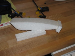
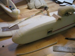
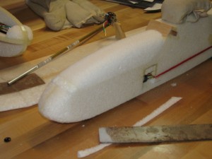
    Roughing the canopy

    Cut away anything that doesn't look like a canopy.

  7. Top and bottom tail boom reinforcements for stiffness and durability (kraft paper composite on the prototype and carbon fiber in production.)
  8. Revised and improved taping schedule using Scotch clear duct tape instead of fiberglass reinforced packing tape for weight reduction.
  9. Revised servo placement and servo recommendations (from HS-81 to HS-65 servos) for better weight distribution, durability, and reduced overall weight.
  10. Servo mounting via embedded rails for ease of maintenance.
  11. Canopy, final shape

    Now it looks like it belongs.

    Design for removable tips has been established but will not be a factory option initially due to the need to source a sheet metal vendor.

  12. “Lite” option replaces balsa wood trailing edge with kraft paper composite.
  13. Three different motor mount options available (10 mm stick-mount, bulkhead mount, and V-block mount.)
An old picture showing the kraft paper composite on the tail boom

The first place I tried kraft paper composite.

Now, throughout this process, I was trying to figure out how to make my idea for using “kraft paper composite” to work in my favor for weight reduction.  I tried it in several placed during this build even through the wing was one of Denny’s old ones with a balsa trailing edge.  I managed to actually make it work pretty well, but in doing so I used things like my “shot bags” to weigh the whole mess down while the polyurethane cured.

Okay, let me back up a bit.  Kraft paper composite is a way I came up with to selectively reinforce and stiffen EPP without dumping money into carbon fiber.  I came up with the idea after remembering some experiments that Pat Mattes did over 10 years ago with old paper shopping bags, latex paint, and a vacuum bagging system.

The long and short of it is this: yes it works.  The tail boom on the V5 prototype is VERY stiff, especially after it was covered with Ultracote.  The down side is that it’s not something I would sic on a beginner.  If you don’t get the weights spread out right, the glue foams up and raises the paper.  Worse, if you aren’t careful, it’d be really, really easy to lay in a twist to a structure that no amount of fancy heat gun work could take out.

First flat cat prototype

How I learned to quit worrying and trust carbon fiber

Worse yet, I think that if you do it wrong, it’s heavier than carbon.  Even if you do it right, it might be heavier, although it’s probably lighter than balsa.  I’m basing that off my experience with the Flat Cat indoor/park flier I built toward the end of the summer.  I’m now a lot more comfortable with using CF in EPP, and I intend to take that direction with the V5 tail boom.

That having been said, there is still a place for the kraft paper composite in the Push-E Cat.  The trick is, however, to not try and put it on with polyurethane glue.  Instead, you use 3M 90 spray adhesive followed by a urethane sealer.  More on that in a bit.

The end result of all this noodling around is that I have finally become comfortable with making all Push-E Cats with tapered tail booms.  That means there’s no real need for a separate “Lite” Push-E Cat.  Instead, I just have to give people who want to buy a kit a series of options:

  1. Do you want a polyhedral wing or aileron wing? (Basically, do you want a bent wing or a flat wing?)
  2. What kind of motor mount do you want? (10 mm stick, bulkhead, or inrunner V-block)
  3. What color do you want your tail coroplast to be? (white, black, sky blue)

The removable tip option will come later after I find a suitable sheet metal supplier.

Shot of V5 cabin showing interior carbon stays

Carbon makes your wing fit right

The tapered rear cabin and single rear hold down dowel will be a build option.  Those wanting to take the easier route of having two dowels in back just like in front will avoid having to carve and sand the cabin.

The other thing that I made sure to do was open up the cabin as much as I could.  As the picture on the right shows, a couple of carbon stays are all that it takes to stiffen the wing saddle and cabin enough to make a difference.  With that, I can now use a router to make a much larger bay under the saddle.  My hope is that this, along with all that available space in the nose, will make the Push-E Cat V5 a viable aerial photography platform.  Lord knows it has enough power and lift.

Detail showing motor mount and wire routing

It's the little details that count.

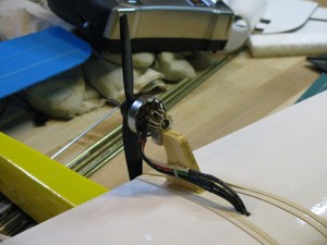
There’s a lot of little points that go into building a Push-E Cat, especially the V5, that go to making the thing more survivable than average.  Like in the photo on the left, where you can see how I used a tie-strap to secure the motor wires to the pylon.  The three black wires that go down through the wing are actually jumpers that connect via bullets to the speed control, thus maintaining the original design intent of having “break away” connections between the wing and the fuselage in case of impact.  That kind of stuff always pops out at me during odd times.

Anyway, rather than letting things pile up as I drive through the remaining issues, I’ll try to keep running short updates daily.  Tomorrow, for example, I’ll show you some pictures of the first kraft paper composite trailing edge center wing panel and talk about how it’s going to make having ailerons (and even flaps, if you want!) easier.

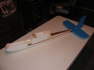
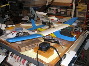
Completed V5 prototype sitting on a very cluttered bench.

Yes, I actually do build things on this bench.

As for kits and availability, I’m now completely done with any conceptual roadblocks and driving to complete the instructions.  When I can’t write anymore, I’ll be out in the shop cutting parts for kits.  Look for an announcement on those shortly.

Posted in Kit Projects, Prototypes, Push-E Cat V5 | Leave a comment

Days Past, but Moving Forward

Darwin with V2 Push-E Cat and prototype Manx

So, how long ago was this?

Welcome to the revived Garrison Aerodrome web portal!

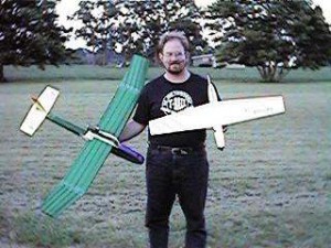
For those of you who don’t know, Garrison Aerodrome is the business persona of me, Darwin A. Garrison.  Back between 1998 and 2001, I put out the Push-E Cat, the Manx, the HotCat, and the Positron kits.  They were all powered by Speed 400 brushed electric motors of various flavors energized by 7 or 8 cell Nickel-Cadmium battery packs.

Sadly, my first stab at this business didn’t hang on very well.  My wife took great affront to the fact that I needed to have a “real job” as opposed to what I was doing.  Worse, I got sideways on the necessary paperwork to keep the State of Indiana happy.  I think the final straw came when two assholes ripped me off of about $700.  Maybe that seems like small change, but it really made me re-think doing the on-line retail marketing thing and that led to me selling kits through Kirk Massey at New Creations R/C.

A shot of the original Hand Cat prototype

Push-E Cat Wing plus scrap EPP = Hand Cat

Now Kirk was always awesome to work with, but the issue with that was the kits made me a lot less money selling through a dealer.  With that factor added in, I kind of lost all incentive to keep at it.

Fast forward 10 years.  The guy I let make Push-E Cat after I stopped dropped out.  I also happened to be out of work.  When I saw that the old Push-E Cat still had a loyal following that was lamenting the loss of the bird from the market, I decided that maybe the time had come for me to take another stab at things, being a bit older and wiser and all.

Actually, the time is better than ripe because of all the positive changes that have happened in direct web-based retail marketing.  I don’t have to do a lot of HTML programming this time around.  Instead, I can use canned programs for everything from WordPress to the shopping cart software to accepting any kind of payment via PayPal.  Thanks to that, the odds of me being shafted by either pseudo-customers have dropped significantly.

Cabin Foamie, three quarter view

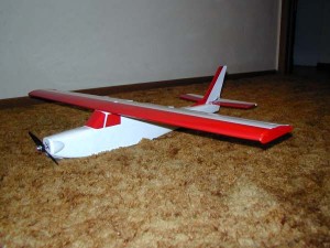
The Cabin Foamie shall rise again!

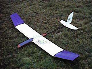
Another thing that bodes well for the return of Garrison Aerodrome is the ready availability of CNC machinery.  I have already ordered a PhlatPrinter (a low-cost-of-entry CNC router) that will allow me to cut fuselages and flat-foam kits very easily.  Building on that, I will construct a CNC hot wire machine using similar electronics.  That way, all of my equipment will function similarly, greatly reducing the learning curve.

Until that all gets going, though, I’ll be doing things the old-fashioned way with my bandsaw, hot wire rig, and router.

I hope you’ll follow along with me as I bring my products into the 21st century of brushless motors and lithium chemistry batteries.  The old shall be new and the new will be a lot of fun!

Posted in News | Leave a comment