Yeah, I’d put something catchier for the post title if I could actually come up with something pithy to say. However, that would be oddly disrespectful to the amount of slog it has taken to get this model put together.
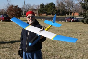
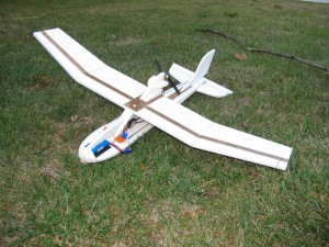
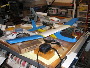
Anyway, have a picture! This is the V5 “semi-light” prototype. It weighs 24.7 ounces using a Towerpro motor with a Master Airscrew 7×5 prop and a 2200 mAh Thunder Power 3S lipo pack. The servos are HS-65’s from Hitec. The receiver is a 7000 series from Spectrum on 2.4. The speed control is the old, nasty Polk 18 amp that Denny used to provide out of Polecat.
Now, I know 24.7 ounces may not seem all that “Lite”. Given, though, how my previously built Push-E Cats tended to come in around 30 ounces back in the day of Speed 400 longs and 8xKR1700 mAh NiCad packs, I’ll take it. The tail feathers on this particular model have excess carbon rods and bamboo stick in them, for example, because I wanted to see how each stiffened the 2mm coroplast. Also, the kraft paper laminate in the tail, while perfectly functional, will probably be replaced with .052x.177 carbon fiber based on my experiences with the Flat cat. More on that in a bit.
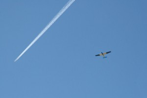
By the way, I love how this prototype flew. The reduced weight plus the performance increase from the TowerPro motor let it really scramble up into the air quickly. The only downer was that the fixed Master Airscrew prop turned into a barn door when I cut the throttle. I’m working on setting up a 3mm compatible folding prop setup to try using an Aeronaut 7×4.5 folder next. All the adapters I have right now are set up for 3.2 mm shafts and that causes issues, oddly enough, ranging from excess vibration with the set-screw types to an inability to clamp for the collet types.
I did a list of the things that I’d consider “improvements” and “features” on the V5. I thought I’d share those with everyone just so you can see that I do actually kind of think things through.
- Extended nose for easier LiPo balancing.
- Magnetic canopy closure.
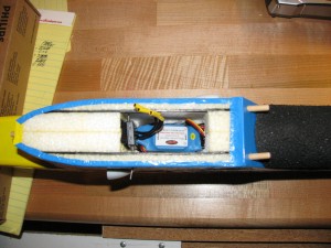
- Flow through cooling for battery and ESC (note that this isn’t present on the prototype. I stuck a side scoop on the cabin because I forgot about this while I was building the fuselage. This will be a production feature and far less intrusive.)
- Tapered tail boom for reduced weight and drag.
- Removable horizontal stab.
- 2 mm Coroplast tail surfaces with carbon fiber reinforcement for weight and drag reduction.
- Top and bottom tail boom reinforcements for stiffness and durability (kraft paper composite on the prototype and carbon fiber in production.)
- Revised and improved taping schedule using Scotch clear duct tape instead of fiberglass reinforced packing tape for weight reduction.
- Revised servo placement and servo recommendations (from HS-81 to HS-65 servos) for better weight distribution, durability, and reduced overall weight.
- Servo mounting via embedded rails for ease of maintenance.
-
Design for removable tips has been established but will not be a factory option initially due to the need to source a sheet metal vendor.
- “Lite” option replaces balsa wood trailing edge with kraft paper composite.
- Three different motor mount options available (10 mm stick-mount, bulkhead mount, and V-block mount.)
Now, throughout this process, I was trying to figure out how to make my idea for using “kraft paper composite” to work in my favor for weight reduction. I tried it in several placed during this build even through the wing was one of Denny’s old ones with a balsa trailing edge. I managed to actually make it work pretty well, but in doing so I used things like my “shot bags” to weigh the whole mess down while the polyurethane cured.
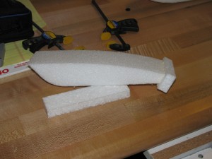
Okay, let me back up a bit. Kraft paper composite is a way I came up with to selectively reinforce and stiffen EPP without dumping money into carbon fiber. I came up with the idea after remembering some experiments that Pat Mattes did over 10 years ago with old paper shopping bags, latex paint, and a vacuum bagging system.
The long and short of it is this: yes it works. The tail boom on the V5 prototype is VERY stiff, especially after it was covered with Ultracote. The down side is that it’s not something I would sic on a beginner. If you don’t get the weights spread out right, the glue foams up and raises the paper. Worse, if you aren’t careful, it’d be really, really easy to lay in a twist to a structure that no amount of fancy heat gun work could take out.
Worse yet, I think that if you do it wrong, it’s heavier than carbon. Even if you do it right, it might be heavier, although it’s probably lighter than balsa. I’m basing that off my experience with the Flat Cat indoor/park flier I built toward the end of the summer. I’m now a lot more comfortable with using CF in EPP, and I intend to take that direction with the V5 tail boom.
That having been said, there is still a place for the kraft paper composite in the Push-E Cat. The trick is, however, to not try and put it on with polyurethane glue. Instead, you use 3M 90 spray adhesive followed by a urethane sealer. More on that in a bit.
The end result of all this noodling around is that I have finally become comfortable with making all Push-E Cats with tapered tail booms. That means there’s no real need for a separate “Lite” Push-E Cat. Instead, I just have to give people who want to buy a kit a series of options:
- Do you want a polyhedral wing or aileron wing? (Basically, do you want a bent wing or a flat wing?)
- What kind of motor mount do you want? (10 mm stick, bulkhead, or inrunner V-block)
- What color do you want your tail coroplast to be? (white, black, sky blue)
The removable tip option will come later after I find a suitable sheet metal supplier.
The tapered rear cabin and single rear hold down dowel will be a build option. Those wanting to take the easier route of having two dowels in back just like in front will avoid having to carve and sand the cabin.
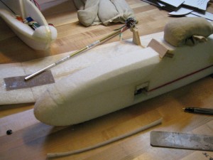
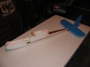
The other thing that I made sure to do was open up the cabin as much as I could. As the picture on the right shows, a couple of carbon stays are all that it takes to stiffen the wing saddle and cabin enough to make a difference. With that, I can now use a router to make a much larger bay under the saddle. My hope is that this, along with all that available space in the nose, will make the Push-E Cat V5 a viable aerial photography platform. Lord knows it has enough power and lift.
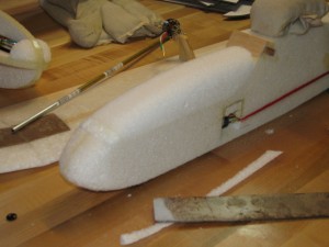
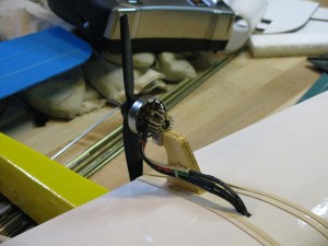
There’s a lot of little points that go into building a Push-E Cat, especially the V5, that go to making the thing more survivable than average. Like in the photo on the left, where you can see how I used a tie-strap to secure the motor wires to the pylon. The three black wires that go down through the wing are actually jumpers that connect via bullets to the speed control, thus maintaining the original design intent of having “break away” connections between the wing and the fuselage in case of impact. That kind of stuff always pops out at me during odd times.
Anyway, rather than letting things pile up as I drive through the remaining issues, I’ll try to keep running short updates daily. Tomorrow, for example, I’ll show you some pictures of the first kraft paper composite trailing edge center wing panel and talk about how it’s going to make having ailerons (and even flaps, if you want!) easier.
As for kits and availability, I’m now completely done with any conceptual roadblocks and driving to complete the instructions. When I can’t write anymore, I’ll be out in the shop cutting parts for kits. Look for an announcement on those shortly.

